ISO 5210 Flange Dimensions
ISO 5210 specifies the requirements for the attachment of multi-turn actuators to valves.
Throughout this document, “actuator” can be understood as “actuator and/or gearbox” providing a
multi-turn and/or linear output.
ISO 5210 specifies:
— flange dimensions necessary for the attachment of actuators to industrial valves [see Figure 1 a)] or
to intermediate supports [see Figure 1 b)];
— those driving component dimensions of actuators which are necessary to attach them to the driven
components;
— reference values for torque and thrust for flanges having the dimensions specified in this document.
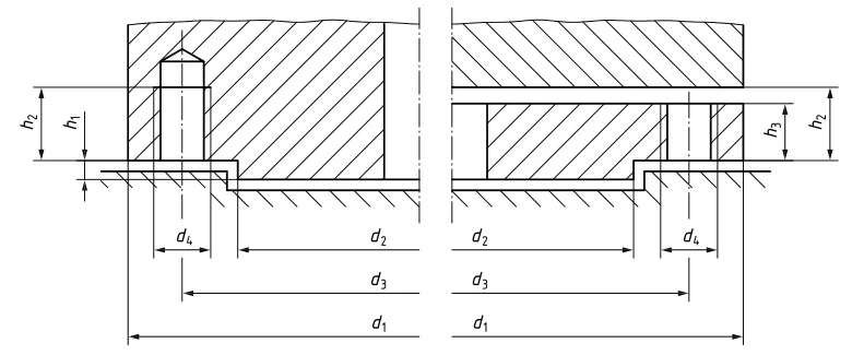
Table 2 — ISO 5210 Flange dimensions
Table 2 — Flange dimensions
Dimensions in millimetres
| Flange type | Dimensions | Number of studs or bolts | ||||||
| d₁ min. | d₂a | d₃ | d₄ | h₁ max. | h₂ min. | h₃ min. | ||
| F05 | Ø65 | Ø35 | Ø50 | M6 | 3 | 9 | 6 | 4 |
| F07 | Ø90 | Ø55 | Ø70 | M8 | 3 | 12 | 8 | 4 |
| F10 | Ø125 | Ø70 | Ø102 | M10 | 3 | 15 | 10 | 4 |
| F12 | Ø150 | Ø85 | Ø125 | M12 | 3 | 18 | 12 | 4 |
| F14 | Ø175 | Ø100 | Ø140 | M16 | 4 | 24 | 16 | 4 |
| F16 | Ø210 | Ø130 | Ø165 | M20 | 5 | 30 | 20 | 4 |
| F25 | Ø300 | Ø200 | Ø254 | M16 | 5 | 24 | 16 | 8 |
| a d₂ shall be manufactured within the diameter tolerance f8. | ||||||||
Table 2 — Flange dimensions (continued)
Dimensions in millimetres
| Flange type | Dimensions | Number of studs or bolts | ||||||
| d₁ min. | d₂a | d₃ | d₄ | h₁ max. | h₂ min. | h₃ min. | ||
| F30 | Ø350 | Ø230 | Ø298 | M20 | 5 | 30 | 20 | 8 |
| F35 | Ø415 | Ø260 | Ø356 | M30 | 5 | 45 | 30 | 8 |
| F40 | Ø475 | Ø300 | Ø406 | M36 | 8 | 54 | 36 | 8 |
| F48 | Ø560 | Ø370 | Ø483 | M36 | 8 | 54 | 36 | 12 |
| F60 | Ø686 | Ø470 | Ø603 | M36 | 8 | 54 | 36 | 20 |
| a d₂ shall be manufactured within the diameter tolerance f8. | ||||||||
Table 3 —Positions of holes
| Flange type | a/2 |
| F05 to F16 | 45° |
| F25 to F40 | 22,5° |
| F48 | 15° |
| F60 | 9° |