ISO 28921-2: Industrial valves —Isolating valves for low-temperature applications
Part 2: Type testing
ISO 28921 Part 2 specifies requirements for the type testing of isolating valves for low-temperature applications to verify the performance of valves at a low temperature from – 50 °C down to – 196 °C.
NOTE Nominal sizes (DN), nominal pipe sizes (NPS), nominal pressure (PN) and Classes are covered in ISO 28921-1.
ISO 28921 Part 2 does not evaluate valve actuators unless they are integral part of the valve.
Valves during testing can be operated manually or an actuator can be used during the testing. The effect of cold gas vapours during testing is taken into consideration in particular if the actuator is mounted directly over the test stand with the cold gases engulfing the actuator.
ISO 28921-2 does not apply to valves for cryogenic services, designed in accordance with ISO 21011, used with cryogenic vessels.
Annex A
(normative)
Test procedure for type testing of valves at low temperature
A.1 General
The following procedure covers the testing for sealing and operability of valves at one of the following temperatures:
a) valve tests at – 196 °C;
b) valve tests at – 50 °C;
c) an alternative temperature of between – 50 °C and – 196 °C may be used.
The test temperature shall not be less than the minimum design temperature of the valve. For low temperature suitability of metallic materials, use ASME B31.3 or EN 13480-2.
A.2 Test procedures
A.2.1 Testing flow chart
See Figure A.1.
A.2.2 Ambient temperature test
A.2.2.1 Valve tests
Shell and seat testing shall be in accordance with ISO 5208. The shell test pressure shall be 1, 1 × CWP if tested with gas or 1, 5 × CWP if tested with alcohol or water. The seat closure test pressure shall be at (6 ± 1) bar 1 ). For soft seated valves, the seat leakage rate shall be in accordance with ISO 5208, Rate A. For metal seated valves, it shall be according to the valve manufacturer’s standard. After each test is complete, the valve shall be thoroughly dried.
A.2.2.2 System proving test
A.2.2.2.1 Test pressure
A system proving test shall be performed at the maximum valve cold working pressure or maximum seat test pressure, whichever is lower.
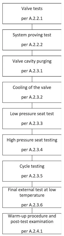
Figure A.1 — Testing flow chart
A.2.2.2.2 Test procedure
The test valve as well as all the connected tubing or piping shall be inspected for leakage while pressurized to CWP. For external leakage detection, a soap solution or helium leak detector shall be used.
During this test the test valve shall be in full open position except for check valves, the valve shall be in closed position and the pressure shall be applied in the normal flow direction. Any detected leakage shall be eliminated.
A.2.3 Low-temperature test
A.2.3.1 Valve cavity purging
A purge of test gas at a supply pressure of (2 ± 0, 5) bar 1) shall continuously flow through during cool down. Metal seated valves shall be in a half-open position, while for soft seated ball valves the closure member shall be in the fully open position and shall only be operated for cavity purging. For check valves, the test gas flow shall be in a direction to open the obturator.
A.2.3.2 Cooling of the valve
If the cooling media is liquid, the test valve shall be slowly submerged in the coolant to a depth such that the level of the coolant covers at least the top of the valve body to bonnet joint. For check valves, the entire valves shall be submerged in the coolant.
If the spraying method with cooling medium is used, then the test valve shall be completely sprayed, including the valve body to bonnet joint.
If the cooling media is cold gas, the valve shall be installed in the cooling tank so that the valve body and the body to bonnet joint are exposed to the cold gas. During the valve cooling, the purge of test gas shall be maintained.
A.2.3.3 Low-pressure seat test
When the test valve is at the designated test temperature, the purge of the test gas shall be turned off. The test valve shall be operated to the full open position, and pressurized to (2 ± 0, 5) bar 1) with the test fluid.
With the downstream isolation valve open (see Figure 1) and test gas flowing through the valve, the valve shall be then closed and the (2 ± 0, 5) bar 1) pressure shall be re-established. The valve shall be then fully opened and closed five times, while each time, the gas pressure upstream of the test valve shall be re-established.
The closing and opening torque shall be measured and recorded during the first and the fifth operation cycle. After completion of the last open-close cycle and after the pressure and leakage stabilization hasoccurred, the seat leakage shall be measured and recorded.
For check valves, the seat leakage shall be measured across the closed obturator applying the pressure in the reverse direction to the normal flow and there is no need to operate the valve.
A.2.3.4 High-pressure seat testing
The high-pressure seat test shall be performed and recorded in four equal pressure increments, beginning with the firstincrement at a quarter of the valve allowable cold working pressure or maximum operating pressure when specified.The last increment shall be equal to the allowable CWP.Except for actuated valves where the actuator size is specified and selected for operation at a differential pressure less than CWP, the high pressure seat test may be reduced based on the specified differential pressure. The seat test pressure may also be limited by the valve design, the seat test pressure may be reduced based on the valve manufacturer's standard.
During each pressure increment, enough time shall be allowed to stabilize the pressure and the test temperature (see Clause A.5).The seat leakage as well as the valve seating and unseating torque shal be measured and recorded during each pressure increment.
For check valves, the seat leakage shall be measured across the closed obturator applying the pressure in the reverse direction to the normal flow and there is no need to operate the valve.
A.2.3.5 Cycle testing
A.2.3.5.1 Operation of the valve against full differential pressure
After the last pressure incremental test above, the test valve shall be closed, pressurized to CWP, the downstream valve opened to depressurize the downstream tubing or piping.The test valve shall be operated from full close to full open position five times, after each venting of the test gas, the full differential pressure across the test valve shall be re-established.The seat leakage shall be measured and recorded after the first and the fifth cycle.
This test requirement does not apply to check valves.
A.2.3.5.2 Operation of the valve without differen tial pressure
The test valve as well as the valve downstream shall be closed, the CWP inside the valve shall be re- established and the test valve shall be operated 180 times from full closed to full open.The speed of operation shall be established based upon manufacturer's recommendation.
This test requirement does not apply to check valves.
A.2.3.5.3 Last operational cycles
After the last valve cycle above, the test valve shall be closed, the CWP pressure upstream the test valve re-established, the downstream valve shall be opened and the seat leakage shall be measured.If the seat leakage is acceptable, the test valve shall be cycled five times with full CWP across the valve.During the last operational cycle, the seat leakage as well as the valve torque shall be measured and recorded.
For check valves, the obturator shall be moved from closed position to open three times by reversing the gas flow and after the third cycle, the seat leakage shall be measured.
A.2.3.6 Final external test at low tem perature
After completion of the high pressure tests, depressurized valve shall be operated five times by opening and closing through its full stroke.The operating force shall not exceed 360 N, except for manual valves, the maximum initial force required for valves seating or unseating shall not exceed 1000 N.
The test valve shall be partially opened, pressurized to the allowable CWP or specified differential pressure and the designated test temperature shall be re-established.
The test valve shall be pressurized for at least 15 min prior to lifting it from the cooling tank.
After the temperature and pressure has stabilized, the valve shall be closed, removed from the cooling tank and checked for external leakage.
For check valves, the tested valve and the connected piping between isolation valve and thermocouple (see items 5 and 7 in Figure 1)shall be pressurized to CWP and the entire assembly shall be lifted out of the cooling tank for the external leakage test.
The valve external leakage for the valve packing and the outside perimeter of the bonnet shall not exceed 50 ppmv2)or 1, 78×10-⁶mbarls-1 per millimetre stem diameter for the packing, and 1, 78×10-7mbarl·s-1 per millimetre seal diameter for the bonnet or body joint.
For the measurement of the external leakage, the leakage shall at no time throughout the duration of the test be higher than the above specified limits for more than 10 s.
A.2.4 Warm-up procedure and post-test examination
A.2.4.1 After the external leakage test, the test valve shall be de-pressurized and shall be allowed to warm up to ambient temperature.A forced warming-up is not permitted.Except for soft seated ball valves, for which the closing member shall be in fully open position, the closure member shall be in the half open position
A.2.4.2 After successful testing, the valve shall be disassembled and all internal parts inspected for any signs of internal damage or galling.All finding shall be carefully recorded and photographed.
A.3 Test temperatures
A.3.1 Ambient temperature
The test is performed at between 5 ℃ and 40 ℃.
A.3.2 Low temperatu re
A.3.2.1 Test is performed at-196℃±5℃.
A.3.2.2 Test is performed at-50℃±5 ℃.
A.3.2.3 When an alternative test temperature of between -50 ℃ and -196 ℃ is specified, all the remaining requirements of this part of ISO 28921 shall be met.
A.4 Test pressures
A.4.1 Low-pressure seat test
The test is performed at (6±1)barl)during the seat test according to ISO 5208 and (2±0, 5)barl) during the low-temperature seat test (see A.2.3.3).
A.4.2 Incremental high-press ure seat test
The actual gas pressure during the seat test shall stabilize within±1 barl)for valves up PN 40 (Class 300)and±3 bar1)for higher pressure valves.
A.5 Duration of seat test
The duration of each seat test shall be at least:
一 3 min for valves DN 10 to DN 400, NPS 3/8 to NPS 16;
一 5 min for valves DN 450 or NPS 18 and larger.
Each time the test valve is pressurized and after the pressure and temperature have stabilized, there shall be a waiting period prior to the start of seat testing of equal to or longer than the minimum required duration of the seat test.
The same minimum duration applies to the actual seat test.
A.6 Direction of seat test
For globe, gate, ball and butterfly valves, the seat test is conducted in the normal or preferred flow direction for the valve.
For check valves, the seat test is conducted in the reverse flow direction of the valve.
For valves with bidirectional sealing, each sealing direction shall be tested separately unless otherwise agreed to by the purchaser.
A.7 Allowable seat leakage rates
The maximum allowable seat leakage shall be in accordance with Table A.1.
Table A.1 —Maximum allowable seat leakage rate per millimetre of nominal seat diameter
| Valve PN —Class | Allowed seat leak mm³/sx DN | |
| Gate, globe, butterfly and ball va lve | Check valve | |
| PN 16 —Class 150 | 50 | 250 |
| PN 25 and PN 40 —Class 300 | ||
| PN 100 and PN 160 —Class 600 Class 800 and Class 900 | ||
| PN 250 —Class 1500 | 100 | |