BS ISO 28921: Industrial valves — Isolating valves for low-temperature applications
Part 1: Design, manufacturing and production testing
1 Scope
ISO 28921 Part 1 specifies requirements for design, dimensions, material, fabrication and production testing of isolation valves for low-temperature applications.
It applies to gate, globe, check, butterfly and ball valves and can be used for other valve types used in low-temperature services.
This part of ISO 28921 covers isolation valves for use in cryogenic temperature service where the design low-temperature service is –50 °C down to –196 °C.
ISO 28921 Part 1 does not apply to valves for cryogenic services, designed in accordance with ISO 21011, used with cryogenic vessels.
Where the requirements of this part of ISO 28921 vary from those given in the valve product standards, the requirements of this part of ISO 28921 apply.
ISO 28921 Part covers valves with body, bonnet, bonnet extension or cover made of metallic materials.
It covers valves of nominal sizes DN: 10; 15; 20; 25; 32; 40; 50; 65; 80; 100; 125; 150; 200; 250; 300; 350; 400; 450; 500; 600; 650; 700; 750; 800; 850; 900,
corresponding to nominal pipe sizes NPS: 3/8; 1/2; 3/4; 1; 11/4; 11/2; 2; 21/2; 3; 4; 5; 6; 8; 10; 12; 14; 16;18; 20; 24; 26; 28; 30; 32; 34; 36,
and applies to pressure designations:
— PN 16; 25; 40; 100; 160; 250.
— Class 150; 300; 600; 800; 900; 1500.
NOTE PN 250 and Class 1 500 in sizes DN > 100 and NPS > 4 are not covered in this part of ISO 28921.
4 Requirements
4.1 Materials
4.1.1 General
Materials in contact with cold process fluid or exposed to low temperatures shall be suitable for use at the minimum design temperature specified by the purchase order.Galling, friction heating, galvanic corrosion and material compatibility with the fluid shall also be considered in the selection of materials.
4.1.2 Metallic materials
4.1.2.1 Pressure-retaining bound ary
For material suitability at low temperature, use ASME B31-3 or EN 13480-2.
Body, bonnet, bonnet extension and cover, and other parts of the pressure retaining boundary, shall be selected from materials listed in ASME B16-34 or EN 12516-1 for Class-designated valves or EN 12516-1 for PN designated valves.
4.1.2.2 Bolting
Unless otherwise specified by the purchaser, bolting forassembling shell pressure-retaining components shall be selected from materials listed in ASME B16-34 for Class-designated valves or EN 1515-1 for PN- designated valves.
If low-strength bolting, such as non-strain hardened austenitic stainless steel, for example ISO 3506-1 grade A1-50 and A4-50 or ASTM A320 and ASTM A193 grade B8 Class 1 is being used, the design shall comply with ASME Boiler and Pressure Vessel Code, Section VIII, Division 1 or 2.
4.1.2.3 Internal metallic parts
Internal metallic parts, e.g.stem, wedge, disc, seats, back seat and guide bushings, shall be made of materials suitable for use at the entire design temperature range.
4.1.3 Internal non-metallic materials
Valve parts, e.g packing gasket, seatings and other non-metallic valve parts exposed to low temperature, shall be capable of functioning at the entire design temperature range.
4.2 Design
4.2.1 General
Unless otherwise specified in the purchase order, valves shall have a bonnet extension that protects the stem packing and valve operating mechanism from the low-temperature fluid that could otherwise damage or impair the function of these items.
This part of ISO 28921 shall be applied in conjunction with the specific requirements of a valve product standard, such as ISO 10434, ISO 10631, ISO 14313, ISO 15761 and ISO 17292 or other recognized standards, suchas API, ASME or EN, based on an agreement between the purchaserand the manufacturer.
4.2.2 Body/bonnet wall thic kness
The minimum valve body and bonnet wall thickness shall meet the requirements of ASME B16-34 or EN 12516-1forClass-designatedvalvesand EN 12516-1, EN 12516-2or EN 12516-3for PN designated valves. The pressure rating of the valve at or below service temperatures -50 ℃ shall not exceed the pressure rating at room temperature for the applicable valve body material and appropriate Class or PN designation.
4.2.3 Body and bonnet extension
4.2.3.1 The length of the extension shall be sufficient to maintain the stem packing at a temperature high enough to permit operation within the temperature range of the packing material.
4.2.3.2 The minimum vapour column length or bonnet extension shall be in accordance with Table 1or Table 2 and Figure 1 , unless otherwise specified in the purchase order.
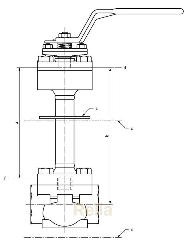
a Minimum vapour column length for non-cold box application (see Table 1).
b Extension for cold box application (see Table 2).
c Outline of cold box enclosure.
d Bottom of the packing chamber.
e Optional drip plate.
f Top of stem guide or bonnet.
Figure 1 — Valve with extended bonnet
Table 1—Minimum vapour column length for non-cold box extension
| Valve size range DN | Minimum vapour column length mm | Valve size range NPS | |||
| Minimum design temperature ℃ | |||||
| minimum | maximum | minimum | maximum | ||
| -196 | -110 | -109 | -51 | ||
| DN≤25 | 200 | 100 | NPS≤1 | ||
| 32≤DN≤65 | 250 | 125 | 144≤NPS≤212 | ||
| 80≤DN≤125 | 300 | 150 | 3≤NPS≤5 | ||
| 150≤DN≤200 | 350 | 175 | 6≤NPS≤8 | ||
| 250≤DN≤300 | 400 | 200 | 10≤NPS≤12 | ||
| 350≤DN≤400 | 450 | 250 | 14≤NPS≤16 | ||
| 450≤DN≤650 | 500 | 300 | 18≤NPS≤26 | ||
| 700≤DN≤850 | 600 | 400 | 28≤NPS≤34 | ||
| DN 900 | 700 | 500 | NPS 36 | ||
Table 2 —Minimum bonnet extension length for cold box applications
| Valve size DN | Minimum bonnet extension length mm | Valve size NPS | |
| Rising stem valvesa | Quarter-turn valves | ||
| DN≤25 | 450 | 400 | NPS≤1 |
| 32≤DN≤65 | 550 | 500 | 114≤NPS≤212 |
| 80≤DN≤125 | 650 | 600 | 3≤NPS≤5 |
| 150 | 760 | 610 | 6 |
| 200 | 865 | 660 | 8 |
| 250 | 1120 | 710 | 10 |
| 300 | 150 | 810 | 12 |
| 350 | 1200 | 850 | 14 |
| 400 | 1300 | 850 | 16 |
| 450 | 1400 | 900 | 18 |
| 500 | 1500 | 950 | 20 |
| 600 | 1600 | 1000 | 24 |
| 650 | 1700 | 1050 | 26 |
| 700 | 1800 | 1100 | 28 |
| 750 | 1900 | 1150 | 30 |
| 800 | 2000 | 1200 | 32 |
| 850 | 2100 | 1250 | 34 |
| 900 | 2200 | 1300 | 36 |
a For globe valves, bonnet extension is shown up to DN 300-NPS 12 only.
4.2.3.3 In case of a bonnet extension made of material having lower pressure/temperature rating than the body, then the extension thickness shall be increased proportionally to meet the pressure/temperature
rating of the body at all applicable temperatures.The minimum wall thickness shall be in accordance with ASME B16-34 for Class-designated valves or EN 12516 for PN designated valves.
4.2.3.4 Bonnet extension tube thickness shall take into account pressure stresses as well as operating torque, stem thrust and bending stresses induced by operating devices, such as handles, gears or actuators.
4.2.3.5 Stem to extended bonnet clearance should be minimized to reduce convective heat loss except there shall be sufficient clearance to avoid interference during operation.
4.2.3.6 Valves specified to be in gas service shall be capable of operation with the extended bonnet in any position, unless otherwise limited by the manufacturer.
4.2.3.7 Valves specified to be in liquid service, other than cold box applications, shall be capable of operation with the extended bonnet at or above 45°above the horizontal position (see Figure 2).
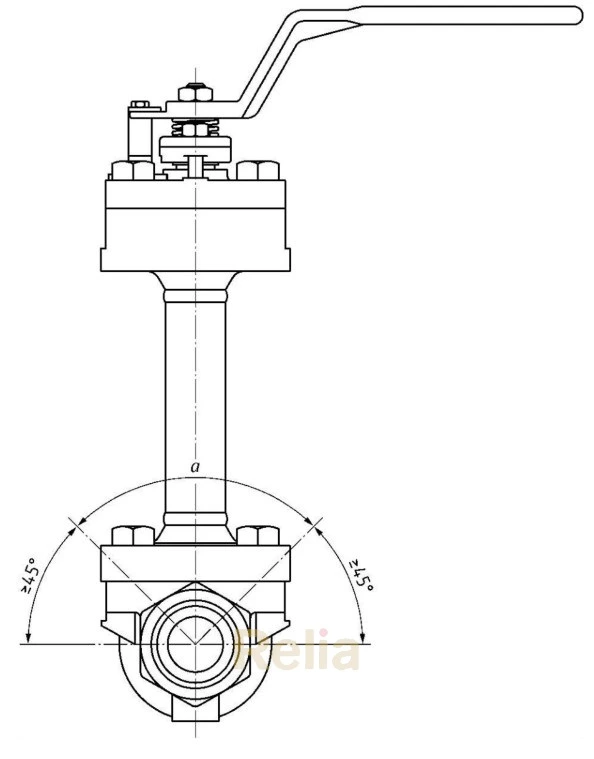 Figure 2 — Recommended bonnet orientation for non-cold box installation
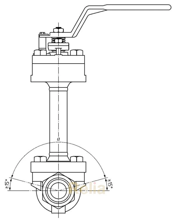
Figure 3 — Recommended bonnet orientation for cold box installation
4.2.3.8 Valves specified to be in cold box applications, equipped with extended bonnet, for applications with liquids, shall be capable of operating with the stem oriented 15°to 90°above the horizontal plane (see Figure 3).
4.2.3.9 A stem guide shall be applied at the lower end of the extended bonnet.
Where necessary, an additional guide may be provided to the upper end of the extension.It shall be located below the packing and designed so as not to interfere or otherwise damage the stem or the packing during normal valve operation.
The guide can be separate or integral with the bonnet extension.
4.2.3.10 Ifspecified on the purchase order, the extension shall be provided with an insulation collar/drip plate.The collar/drip plate may be welded to the bonnet extension or of the clamp-on design.The clamp- on type shall have the bolting on the upper side to enable easy adjustment.Any gap between the bonnet and the collar/drip plate shall be sealed to avoid condensation entering into the insulated area.
4.2.3.11 The extended bonnet may be cast, forged or fabricated.Fabricated extensions shall use full penetration welding except for valves using pipe extension DN 50(NPS 2)or smaller, where partial penetration V-groove welding, fillet type welding or full-strength threaded joint with seal weld may be used.When the bonnet extension is made to a tubular specification, the material shall be seamless.The requirements of ASME B16-34 or EN 12516 shall be met for welds to body/bonnets parts.
4.2.4 Stem
4.2.4.1 Gate and globe valve stems shall have a diameter to length ratio that precludes buckling while under compressive loading, required to fully seat the valve.
4.2.4.2 Backseats, when utilized, may be at the bottom or at the top of the body/bonnet extension. Backseats at the bottom of the extension may increase the risk of pressure build-up in the body/bonnet extension cavity if the valve is backseated and allowed to warm to ambient temperatures.In all cases, the valve manufacturer shall provide a means of protection against cavity over-pressurization.
4.2.4.3 The stem shall be sized in such a way that it is able to transfer the required torque and thrust to the valve and fully seat and unseat the closing element against pressure.Consideration shall be given to any additional stresses resulting from the operational loads.During the stem calculations, the highest valve rated temperature shall be used to establish the allowable material stress.
4.2.4.4 The stem shall be of one-piece construction and it shall be designed so that the stem seal retaining fasteners alone do not retain the stem.
4.2.5 Seats and seatin g surfaces
Metallic seating surfaces in metal seated valves shall have edges equipped with a radius or chamfer as necessary to prevent galling or other damage during operation.
4.2.6 Provision for internal pressure relief
4.2.6.1 Double seated valves shall be designed to prevent the build-up of body cavity pressure due to thermal expansion or evaporation of trapped liquid in excess of 1, 33 times the valve rated pressure. Valves with backseat primary stem seal or stem guide at the bottom of the extension shall be designed to relieve excessive pressure in the bonnet when warmed up to ambient temperature.
4.2.6.2 Unless otherwise specified, pressure reliefshall function as follows:
一 for upstream sealing valves, reliefshall be to the downstream side of the closing member;
一 for downstream sealing valves, reliefshall be to the upstream side of the closing member.
For gate valves, pressure reliefshall be achieved by the use of a relief hole, located so as to relief excess cavity pressure to the upstream side of the valve when the valve is closed.
Where valve size permits, the pressure relieving hole shall be a minimum of 3 mm in diameter and visible through the valve end-connection when the valve is closed.Where valve size does not permit a 3 mm hole, a smaller hole diameter may be used.
4.2.6.3 For ball valves with polymeric pressure relieving seats, the manufacturer shall demonstrate by type testing that the seats relieve internal pressure at less than 1, 33 times the rated pressure at both the minimum and the maximum design temperature.
4.2.6.4 Double seated valves with a pressure-relieving feature, such as a hole through the body or closure member, are unidirectional and the sealing direction shall be clearly marked on the valve in accordance with Clau se 7.
4.2.7 0perating means
The maximum continuous force required to manually operate the valve under service conditions, when applied at the rim of the handwheel or lever, shall not exceed 360 N.For valves that are not equipped
with gears or manual overrides, the maximum initial force required for valves seating or unseating shall not exceed 1000 N
4.2.8 Electric continuity and fire-safe design
Valves with soft seats or soft closing member insert to be used with flammable vapours or liquids shall be designed in such a way that there is electric continuity between the body and stem of the valve.The maximum electrical resistance shall not exceed 10 Ω across the discharge path.To test for continuity, a new, dry valve shall be cycled at least five times, and the resistance can then be measured using DC power source not exceeding nominal 12 V.
When service conditions require that a fire-type test be conducted, this test shall be in accordance with ISO 10497 or API 607 or API 6FA.
5 Testing
5.1 Production testing with low-temperature test
5.1.1 A specified number of valves according to Table 3 shall undergo low-temperature production testing.Prior to the low-temperature testing, all valves shall be ambient-pressure tested as specified in Annex A.After the test, the valves shall be dried and degreased internally unless the shell and seat tests were performed with cleaned valve and dry gas.
5.1.2 The test gas shall be helium.However, for seat testing at temperatures above -110 C, nitrogen mixed with 10 %helium making up the balance may be used.
5.1.3 Thetype ofcoolantshall beliquid nitrogen fortestingatatemperature of-196C.Fortemperatures higher than-196°℃, nitrogen gas or dry ice, mixed with heat transfer fluid shall be used, unless otherwise agreed between the manufacturer and the purchaser.
5.1.4 The test temperature shall be in accordance with minimum valve design temperature or as specified by the purchaser.A temporary temperature variation for any thermocouples within a range of ±5 %and not exceeding±5 ℃ are acceptable.
5.1.5 For low-temperature testing at-196 ℃ or at-50 ℃, the test procedure in An nex Ashall be used. For other test temperatures, the procedure shall be modified accordingly.
5.1.6 After the test, the valve shall be visually inspected and, if found in satisfactory condition, it shall be thoroughly cleaned, degreased and dried.Disassembly of valve is not required.
5.1.7 All test data shall be recorded.After completion of the testing and final examination, test results shall be documented in a test report.The test report shall include the name of the testing organization, responsible individual, and any purchaser and/or supplier witnesses present during the test.An example of a low-temperature test record is provided in Annex B.