API 6FA: Standard for fire test for valves
API 6FA is to establish, the require- ments for testing and evaluating the pressure-containing performance of API 6A and 6D valves when exposed to fire.
1 Scope
API 6FA is to establish, the require- ments for testing and evaluating the pressure-containing per- formance of API 6A and 6D valves when exposed to fire. The performance requirements of this document are intended to establish standard limits of acceptability regardless of size or pressure rating.
This document establishes acceptable levels for leakage through the test valve and also external leakage after exposure to a fire for a 30 minute time period.
The burn period has been established on the basis that it represents the maximum time required to extinguish most fires. Fires of greater duration are considered to be of a major magnitude with consequences greater than those anticipated in this test.
3 Test Procedure
3.1 STEPWISE PROCEDURES (REFER TO FIGURE 4)
3.1.1
Open valve(s) (Item 5 and 6) at water source, and any necessary vent valves (Item 17) to flood the system and purge the air. The test valve may have to be placed in the partially open position in order to completely flood the valve body.
3.1.2
Close fill valve (Item 5) and test valve (Item 11), then close vent valves (Item 17). The piping system upstream of the test valve shall be completely water filled and the system downstream shall be drained.
3.1.3
Pressurize the system to the appropriate high test pressure from Table 1. Maintain this pressure during the burn and cool-down period. Momentary pressure losses are permissible, provided their cumulative recovery time is less than two minutes. Record the reading on the calibrated sight gauge (Item 4). Empty the graduated downstream container (Item 19).
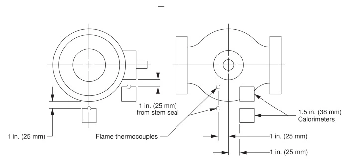
Figure 1—Location of Calorimeters Smaller Valves
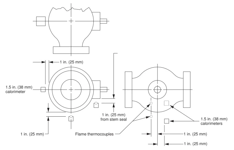
Figure 2—Location of Calorimeters Larger Valves (References 2.2)
3.1.4
Open fuel supply, establish a fire a monitor the flame temperature. The average of two thermocouples (Item 14) must reach 1,400°F (761°C) within two minutes. Maintain the average temperature between 1,400°F–1,800°F (761°C–980°C), with no reading less than 1,300°F (704°C) for the remainder of the burn period.
3.1.5
The average temperature of the calorimeters (Item 13) shall reach 1,200°F (650°C) within 15 minutes of fire ignition. For the remainder of the burn period the calorimeters shall maintain a minimum average temperature of 1,200°F (650°C) and none of the calorimeters shall have a temperature less than 1,050°F (565°C).
Note: Impingement of water or steam from external leakage onto flame thermocouples or calorimeters can result in a substantial drop in the indicated temperature of the affected sensor(s), even if no actual drop in flame temperature has occurred. Such drops in indicated temperatures shall be noted in the test report. The test may continue with no downward adjustment of the burner controls provided that at least one flame thermocouple and one calorimeter are functioning.
3.1.6
Record instrument readings (Items 7, 13, 14, and 15) every 30 seconds during the burn period.
3.1.7
At the end of the burn period (30 minutes), shut off the fuel.
3.1.8
Immediately determine the amount of water collected in calibrated container (Item 19) to establish total through valve seat leakage. Continue collecting water in the calibrated container (Item 19) for use in establishing the external leakage rate.
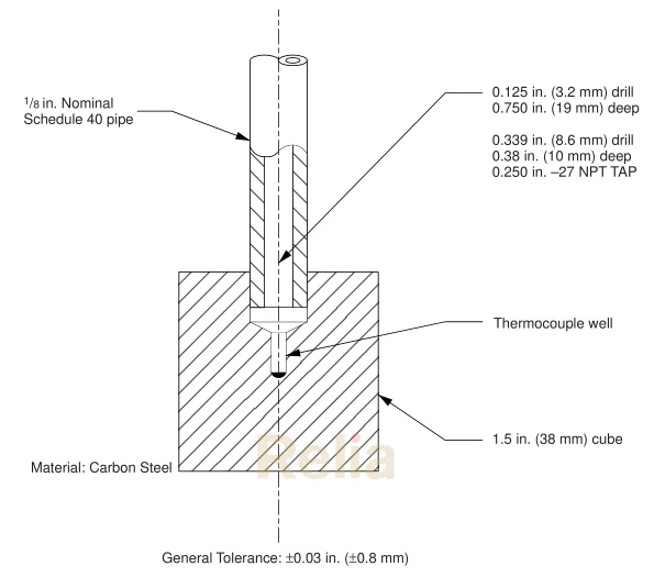
Figure 3—Calorimeter Cube Design (Reference 2.2)
If the test valve is of the upstream sealing type, the volume of water that is trapped between the upstream seat seal and the downstream seat seal, when the valve is closed, shall be determined before the test is started and identified in the test report. It is assumed that during the test this volume of water would move through the valve, past the downstream seat seal and be collected in the calibrated container. Since this volume has not actually leaked past the upstream seat seal, it may be deducted from the total volume measured in the downstream calibrated container when determining the through valve leakage.
Note: If the total volume collected downstream during the burn and/or cooldown is less than the body cavity volume, the through leakage can be assumed to have been zero.
3.1.9
Cool the valve (or allow to cool) to 212°F (100°C) or less. Record reading on sight gauge, (Item 4) and calibrated container (Item 19). Cooling may, at the manufacturer’s option, be natural or forced.
3.1.10
The following low pressure test is required only for API 6D valves with ratings of class 600 and lower. Decrease the test pressure to the low test pressure valve shown in Table 1. Measure the through valve and external leakage over a 5 minute period.
3.1.11
If step 3.1.10 was performed, increase pressure on test valve to the high test pressure valve in Table 1.
3.1.12
Open the test valve against the high test pressure differential. The valve shall be moved to a partly open(approximately half-way) position close to the shutoff valve (Item 16). Vent the piping and test valve body cavity to remove air or steam.
3.1.13
Measure and record external leakage for a period of five minutes after valve is in the open position at high test pressure.
3.2 TEST ADJUSTMENTS
The test system, excluding the test valve, may be adjusted during the test period to keep the test within the limits specified herein.
4 Performance Requirements
4.1 THROUGH LEAKAGE (HIGH TEST PRESSURE)—DURING BURN PERIOD
The maximum through seat leakage shall not be greater than the value shown below (refer to 3.1.8):
Burn Period: 30 minutes
Rate: 400 ml/in./min 1
(15.7 ml/mm/min)
Note: 1 Leakage rates are milliliters per inch of nominal valve size per minute (milliliters per millimeter of nominal valve size per minute), averaged over the duration of the particular test period.
Table 1—Test Pressure During Fire Test
| Valve Rating | High Test Pressure | Low Test Pressure | |||||||
| Class | (PN)a | psi | (bar) | (MPa) | psi | (bar) | (MPa) | ||
| Spec 6D Valves | 150 | (20) | – | 210 | (14,5) | (1,5) | 29 | (2,0) | (0,2) |
| 300 | (50) | – | 540 | (37,2) | (3,7) | 50 | (3,4) | (0,34) | |
| 400 | (64) | – | 720 | (49,6) | (5,0) | 70 | (4,8) | (0,48) | |
| 600 | (110) | – | 1080 | (74,5) | (7,5) | 105 | (7,2) | (0,72) | |
| 900 | (150) | – | 1620 | (111,7) | (11,2) | – | – | – | |
| 1500 | (260) | – | 2700 | (186,2) | (18,6) | – | – | – | |
| 2500 | (420) | – | 4500 | (310,3) | (31,0) | – | – | – | |
| psi | (bar) | (MPa) | psi | (bar) | (MPa) | ||||
| Spec 6A Valves | 2000 | (138) | (13,8) | 1500 | (103,4) | (10,3) | – | – | – |
| 3000 | (207) | (20,7) | 2250 | (155,1) | (15,5) | – | – | – | |
| 5000 | (345) | (34,5) | 3750 | (258,6) | (25,9) | – | – | – | |
| 10000 | (690) | (69,0) | 7500 | (517,1) | (51,7) | – | – | – | |
| 15000 | (1034) | (103,5) | 11250 | (775,7) | (77,6) | – | – | – | |
| 20000 | (1379) | (138,0) | 15000 | (1034,2) | (103,5) | – | – | – | |
a PN is the pressure class designation utilized in ISO (International Standards Organization) documents.
Tolerance on all test pressures is ± 10%.
4.2 EXTERNAL LEAKAGE (HIGH TEST PRESSURE)—DURING BURN AND COOL-DOWN PERIOD (VALVE IN CLOSED POSITION)
The maximum external leakage shall not be greater than the value shown below (refer to 3.1.8 and 3.1.9):
Test Duration: 30 minutes plus time to cool-down to 212°F (100°C)
Rate: 100 ml/in./min1
(3.9 ml/mm/min)
4.3 THROUGH LEAKAGE (LOW TEST PRESSURE)—AFTER COOL-DOWN
The maximum through seat leakage shall not be greater than the valve shown below (refer to 3.1.10):
Test Duration: 5 minutes
Rate: 40 ml/in./min1
(1.6 ml/mm/min)
4.4 EXTERNAL LEAKAGE (LOW TEST PRESSURE)—AFTER COOL-DOWN (VALVE IN CLOSED POSITION)
The maximum external leakage shall not be greater than the value shown below (refer to 3.1.10):
Test Duration: 5 minutes
Rate: 20 ml/in./min 1
(0.8 ml/mm/min)
4.5 OPERATION OF TEST VALVE AFTER FIRE TEST
The valve shall be capable of being unseated from the closed position against high test pressure differential (Table 1).
The valve shall be moved to the open position one time (as specified in 3.1.12).
4.6 EXTERNAL LEAKAGE—OPEN POSITION
With the test valve in the open position the external leakage (as determined in 3.1.13) shall not be greater than 200 ml/in./ min (8 ml/mm/min).
4.7 PRESSURE RELIEF PROVISION
The valve fails the test if the pressure relief valve identified in the provision of 6.2 activates. However, if the relieving device activates in the test valve which normally includes the pressure relieving device as standard, the test shall continue and any leakage through this device shall be counted as external leakage.
4.8 TESTS REQUIRED
In lieu of testing each size and pressure rating of a given valve design, other valves of the same basic design as the test valve and same nonmetallic materials with respect to the seat to closure member seal, seat to body seal, stem seal and body joint and seal, may be qualified, subject to the following limitations:
4.8.1
One test valve may be used to qualify valves larger than the test valve, not exceeding twice the size of the test valve (refer to Table 2). A size 16 valve will qualify all larger sizes.
4.8.2
One test valve may be used to qualify valves with higher pressure ratings but no greater than twice the pressure rating of the test valve (refer to Table 3).
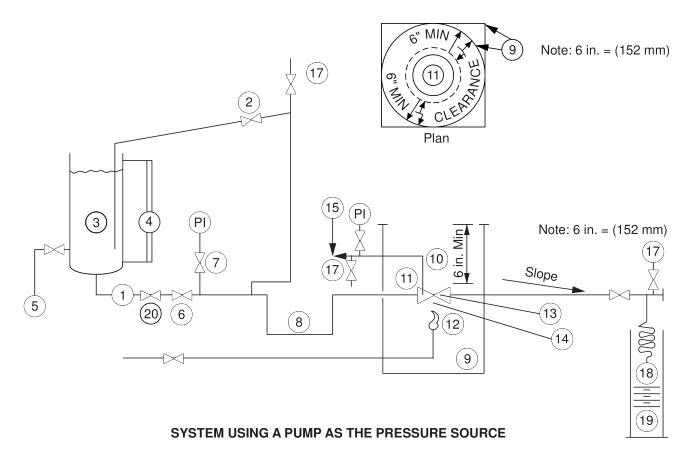
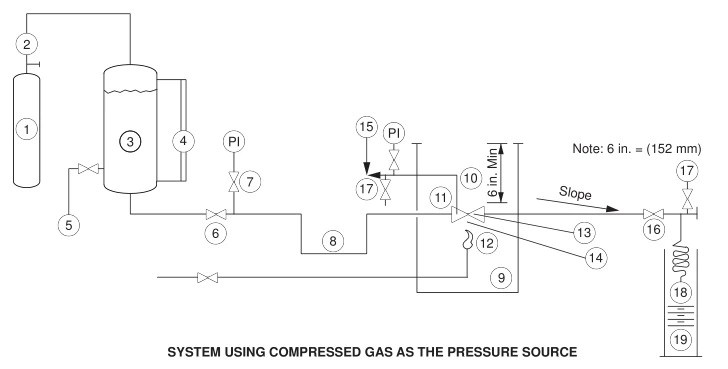
Legend
1 . Pressure source.
2. Pressure regulator and relief.
3. Vessel for water.
4. Calibrated sight gauge.
5. Water supply.
6. Shutoff valve.
7. Pressure gauge.
8. Piping arranged to provide vapor trap.
9. Enclosure for test—horizontal clearance between any part of the
valve and the closure shall be a minimum of 6 in. (1 52 mm).
1 0. Minimum height of enclosure shall be 6 in. (1 52 mm) above
the top of the valve.
11 . Test valve mounted horizontally with stem in horizontal position.
1 2. Fuel gas supply to burners (Ref. 2.2).
1 3. Calorimeter—1 1 / 2 in. cubes (Ref. 2.2).
1 4. Flame temperature thermocouple (Ref. 2.2).
1 5. Pressure gauge and relief valve (if required—Ref. 6.2)
connected to center cavity of valve.
1 6. Shutoff valve.
1 7. Vent valve.
1 8. Condenser.
1 9. Calibrated container.
20. Check valve.
Figure 4—Schematic of Suggested Systems for Fire Test for Valves
4.8.3
The nominal size of the test valve is determined by the size of the end connections.
4.8.4
Valves with asymmetric internal or external body construction (exclusive of the end connections), and/or asym-metric seats and closure mechanism, intended for bi-directional installation shall be qualified by conducting the test procedure twice, once in each direction of potential installation. Asymmetric valves intended for single direction installation shall be marked accordingly and shall be tested in the direction of recommended installation.
4.8.5
Valves shall not be protected with insulation materialof any form during testing, except where such protection is part of the design of the component.