API 6D Welding Specifications
API 6D welding specifications api 6d welding specifications for qualification, inspection and testing, and repairation for weld overlay, hard-facing weld overlays,corrosion resistant alloy (cra) weld overlays.
7 Welding
7.1 General
Section 7, shall not apply to material surface property control, such as thermal spray process [e. g high velocity oxygen fuel (HVOF)]
7.2 Outsourced Welding
NOTE See API 20G for guidance on the use of outsourced Welding Services.
7.3 Consumables
Welding consumables shall conform to the American Welding Society or manufacturer's specifications. The manufacturer shall have a written procedure for storage and control of welding consumables. Materials of low- hydrogen type (including electrodes, wires, and fluxes) shall be stored and used as recommended by the manufacturer of the welding consumable to retain their original low-hydrogen properties.
7.4 Qualification
Welding, including repair welding, of pressure-containing and pressure-controlling parts shall be performed in conformance with procedures qualified to 7.4, 7.5 and 7.6 in addition to ASME BPVC, Section IX; or, qualified to ISO 15607, ISO 15609, ISO 15614-1and ISO 15614-7.
Welders and welding operators shall be qualified in conformance with ASME BPVC, Section IX, ISO 9606-1, or ISO 14732.
NOTE The purchaser, pipeline design standards, material specifications, and/or local requirements may specify additional requirements.
The results of all qualification tests shall be documented in a PQR.
PWHT shall conform to the applicable material specification or design code.
7.5 Weld Overlay
7.5.1 General
Qualification of all weld overlay shall conform to ASME, BPVC, Section IX or to ISO 15614-7.
Hardness survey requirements shall be applied in conformance with the requirements of NACE MR-0175/ ISO 15156 when the valves are specified for use in this service.
7.5.2 Hard-facing Weld Overlays
7.5.2.1 General
Weld overlays for hard-facing shall be applied to thickness and other limitations as detailed in the manufacturer’s qualified welding procedure (WPS and PQR).
7.5.2.2 Visual Inspection
Parts with hard facing shall be visually inspected in conformance with applicable industry material specification.
7.5.3 Corrosion Resistant Alloy (CRA) Weld Overlays
7.5.3.1 General
For any CRA weld overlay with nickel-based alloy UNS N06625, the weld metal chemical analysis at the final qualified minimum cladding thickness identified on the procedure qualification shall be iron dilution class Fe 10: iron mass fraction 10.0% maximum, unless the purchaser specifies otherwise (see K.13).
The iron dilution achieved at the finished minimum qualified thickness shall be clearly identified on the weld procedure qualification records.
For all other compositions of weld overlay, the chemical analysis of the weld metal shall conform to the manufacturer’s written specification at the minimum qualified thickness.
7.5.3.2 NDE in the Final Supplied Condition
CRA weld overlays in the final supplied condition shall be visually inspected in conformance with ASME BPVC, Section V, Article 9. The following acceptance criteria shall apply:
— Undercut shall not reduce the thickness in the area (considering both sides) to below the minimum thickness.
— Surface porosity and exposed slag shall not be permitted on or within 45 mm of seating surfaces
Surface NDE shall be performed on the weld overlay in the final supplied condition using penetrant testing in conformance with ASME BPVC, Section V, Article 6. Acceptance shall conform to ASME BPVC, Section VIII, Division 1, Appendix 8.
7.6 Impact Testing
Qualifications of procedures for welding of pressure-containing parts and for repair welding shall conform to 7.6.
Impact testing shall be performed on carbon, alloy, and stainless steel (except austenitic grades) for the qualification of procedures for welding on valves with a design temperature below –20 °F (–29 °C).
NOTE Design standards and/or local requirements require impact testing at minimum design temperatures above 20 °F (-29 °C).
Impact test results for full-size specimens shall meet the requirements of Table 4 or Table 5, as applicable. When
sub-sized specimens are used, the Charpy V-notch impact requirements shall be equal to that of the 10 mm x 10 mm specimens multiplied by the adjustment factor listed in Table 6 at the full-size specimen test temperatures.
As a minimum, one set of three weld metal (WM) impact specimens shall be taken from the WM at the location shown in Figure 3. The specimens shall be oriented with the notch perpendicular to the surface of the material.
Multiple sets of weld metal impact specimens shall be required when more than one welding process is used. Weld metal impact testing shall be performed to represent each welding process being qualified.
A set of three impact specimens shall betaken from the heat-affected zone (HAZ) at the location shown in Figure 4. The notch shall be placed perpendicularly to the material surface at a location resulting in a maximum amount of HAZ material located in the resulting fracture.
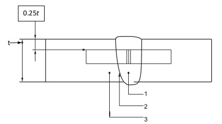
Key
1 weld metal (WM)
2 heat-affected zone (HAZ)
3 base metal (BM)
Figure 3—Charpy V-notch Weld Metal Specimen Location
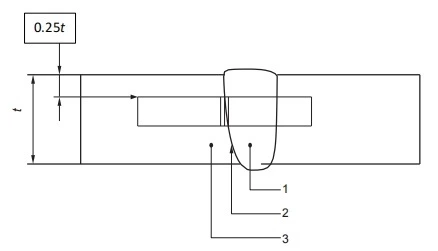
Key
1 weld metal (WM)
2 heat-affected zone (HAZ)
3 base metal (BM)
Figure 4—Charpy V-notch Heat-affected Zone Specimen Location
The HAZ tests shall be conducted for each of the materials being joined when the base materials being joined are of a different P-number and/or group number that conforms to ASME BPVC, Section IX or ISO 9606- 1, ISO 15607, ISO 15609, ISO 15614-1, and ISO 15608 or when one or both of the base materials being joined are not listed in the P- number and/or group number.
Impact testing shall conform to ASTM A370 or ISO 148- 1 using the Charpy V-notch technique. Impact specimens shall be etched to determine the location of the weld and HAZ
The impact test temperature for welds and HAZs shall be at or below the minimum design temperature specified for the valve. Impact test results for full-size specimens shall meet the requirements of 6.4. If the material specification requires higher impact values than those shown in 6.4, the higher values shall apply.
7.7 Hardness Testing
Hardness testing shall be carried out as part of the welding procedure qualification on pressure-containing and pressure-controlling parts in valves required to meet NACE MR0175, ISO 15156 (all parts).
Hardness surveys shall be performed on base metal (BM), WM, and HAZ in conformance with the requirements of NACE MR0175, ISO 15156 (all parts).
7.8 Visual Inspection—Pressure-containing Fillet and Attachment Welds
Fillet and attachment welds to pressure-containing parts shall be visually inspected in conformance with ASME BPVC, Section V, Article 9. The following acceptance criteria shall apply:
― Undercut shall not reduce the thickness in the area (considering both sides) to below the minimum thickness.
― Surface porosity and exposed slag shall not be permitted on or within 1.77 in. (45 mm) of seating surfaces
7.9 Visual Inspection—Pressure-containing and Pipe Pup Welds
Pressure-containing welds and pipe pup-to-valve welds shall be visually inspected in conformance with ASME BPVC, Section V, Article 9. The following acceptance criteria shall apply:
― Undercut shall not reduce the thickness in the area (considering both sides) to below the minimum thickness.
― Surface porosity and exposed slag shall not be permitted on or within 1.77in. (45 mm) of seating surfaces.
7.10 NDE—Pressure-containing and Pipe Pup Welds
For all pressure-containing welds and pipe pup-to-valve welds, surface NDE shall be performed using one of the following methods:
― Magnetic particle testing on weld bevels of weld ends after machining shall conform to ASME BPVC,
Section V, Article 7 and acceptance shall conform to ASME BPVC, Section VIII, Division 1, Appendix 6.
― Penetrant testing on weld bevels of weld ends after machining shall conform to ASME BPVC, Section V, Article 6 and acceptance shall conform to ASME BPVC, Section VIII, Division 1, Appendix 8.
For all pressure-containing welds and pipe pup-to-valve welds, volumetric NDE examination shall be performed using one of the following methods:
― Radiographic testing on 100 % of the welds in accordance with ASME BPVC, Section V, Article 2 and acceptance shall conform to ASME BPVC, Section VIII, Division 1, UW-51 for linear indications and ASME BPVC, Section VIII, Division 1, Appendix 4 for rounded indications.
― Ultrasonic testing on 100 % of the welds in accordance with ASME BPVC, Section V, Article 4 and acceptance shall conform to ASME BPVC, Section VIII, Division 1, Appendix 12.
7.11 Repair
7.11.1 Casting Repair at the Material Supplier
The manufacturer’s written material specification for castings shall specify the limitations for welding repair at the casting material supplier as follows:
― Requirements for qualified weld procedures and qualified welders in conformance with ASTM A488, ASME BPVC Section IX or ISO 15607, ISO 15609, ISO 15614-1and ISO 15614-7 or equivalent,
― Requirement to perform new mechanical testing in conformance with the original material specification, in
case the PWHT temperature is less 50°F (28°C) below the final tempering temperature of the original material. Requirement to perform new mechanical testing in conformance with the original material specification if the PWHT is a solution anneal.
NOTE Per API 20A, repair welding is defect removal resulting in a wall thickness below an acceptable value as specified in purchasing documents.
7.11.2 Casting Repair at the Manufacturer
Repair of defects shall be performed in conformance with a documented procedure specifying requirements for defect removal, welding, heat treatment, nondestructive examination (NDE), and reporting as applicable.
Removal of surface defects shall not compromise the minimum wall thickness and shall provide a smooth transition between the ground area and the original contour. After surface defect removal, the excavated area shall be examined by magnetic-particle (MT) or liquid-penetrant (PT) methods in conformance with Annex I.
After completion, repair welds on pressure-containing parts shall be examined using MT or PT, as well as the same NDE method that was used to identify the defect when another method was used. Acceptance criteria shall be as specified in Annex I for the appropriate product form. The final NDE activities shall be conducted after any required post-weld heat treatment.
Repair weld of castings shall be performed in conformance with the applicable material standard, including any PWHT when required.
When the PWHT temperature is not less than 50 °F (28 °C) below the final tempering temperature of the original material, new mechanical testing shall be performed in conformance with the original material specification.
When the PWHT is a solution anneal, then new mechanical testing shall be performed in conformance with the original material specification.
7.11.3 Forgings and Plate
Weld repair on forgings and plates shall be limited to being performed to only correct machining errors.
Unless otherwise agreed, weld repair of forgings and plates shall not be performed to correct material defects (see K.12).