API 6D Valve Marking Requirement
API 6D Valve marking on valve body, nameplate, including manufacturer's naem, serial number, date of manufacture, material, size, and class rating.
12 Marking
12.1 General
Valve body marking shall conform to the requirements of Table 11.
Table 11—Valve Marking on Body
| Marking | Section | Format | ||
| Manufacturer’s Name* | — | Per Manufacturer Requirements | ||
| Unique Serial Number ** | 14.1 | Per Manufacturer Requirements | ||
| Trademark or Brand name Marks (optional) *** | — | Per Manufacturer Requirements | ||
| Pressure Class or Intermediate Pressure Rating (as applicable) ** | 4.3 | 150, 300, 600, 900, 1500 or 2500 | ||
| Body/closure/end-connector material designation ** a b c | 6 | Material Grade | ||
| Body/closure/end-connector melt identification c | — | Cast or Heat Number | ||
| Nominal valve size ** | Full-opening valves: nominal valve size | 4.4 or 4.5.2 | 8 or DN 200 | |
| Reduced-opening valves: **** | 8 × 6 DN 200 ×150 or 8R x bore or DN 200R x bore |
|||
| Non-circular reduced opening valves | 8R (DN200R) | |||
| SMYS (units) of valve ends, as applicable d | 5.1 | SMYS 40 KSI or SMYS 276 MPa | ||
| Ring joint groove number | c,e | — | R49 | |
| Flow direction (for check valves only) | 4.1.4 | Flow → or ← Flow | ||
| FOOTNOTES * Shall be on either the Body or the Nameplate, minimally. May be on both. ** Shall be on both the Body and the Nameplate *** When Trademark/Brand names are used, the Manufacturer’s Name shall be included **** Bore may be marked in in. or (mm) “—” No specific document reference identified a) When the body is manufactured from more than one type of material, all materials of the body and end connector shall be identified - MSS SP-25 gives guidance on marking b) Body includes body/closure/end - connector c) On body weld ends only. d) On flange OD |
||||
Other valve marking shall conform to Table 12, as applicable.
Body, closure/end connector, and cover/bonnet marking shall be performed using a low-stress die-stamp (rounded “V” or dot face type) or cast.
The marking on the body, end connector, bonnet/cover and nameplate shall be visually legible.
For valves NPS 2 (DN 50) and larger, the marking on the body, closure/end connector and bonnet/cover shall be not less than 0.25 in. (6 mm).
Table 12—Other Valve Marking
| Marking | Format | Location |
| Body/closure/end connector material designation a b | (see Body Marking Requirements) | On both body / closure / end connector and nameplate |
| Body/closure/end-connector melt identification | (see Body Marking Requirements) | On both body/closure/end connector only |
| Bonnet/cover material designation b (see Section 6) | Material Grade | On bonnet/cover |
| Bonnet/cover melt identification (cast or heat number) | A516-70/12345 | On bonnet/cover |
| Seat sealing direction valves with preferred direction. | (see Figure 5) | On separate identification plate affixed to valve body or bonnet/cover or closure/end connector |
| FOOTNOTE a) When the body is manufactured from more than one type of material, all materials of the body and end connector shall be identified. b) Where the grade and class does not uniquely identify the material specification, the material specification, grade, and class shall be marked. Example: A516-70 or A537 CL2, etc. |
||
12.2 Valve Size Marking
Except for reduced-opening valves, valve sizes shall be marked with the nominal pipe size (NPS) or nominal diameter (DN).
Reduced-opening valves with a circular opening shall be marked with the nominal size of the end connectors and the nominal size of the reduced opening in conformance with Table 1 or marked with the nominal size followed by “R” and the actual bore.
EXAMPLE 1 An NPS 16 (DN 400) Class 150 valve with a reduced 11.94 in. (303 mm) diameter circular opening shall be specified as NPS 16 (DN 400) × NPS 12 (DN 300).
EXAMPLE 2 An NPS 16 (DN 400) Class 150 valve with an actual bore 14.75 in. (375 mm) diameter circular opening shall be specified as NPS 16R (DN 400R) x 14.75 in (375mm).
Reduced-opening valves with a noncircular opening and other valves per 4.4.3 shall be marked with the nominal size in conformance with Table 1 corresponding to the end connectors followed by the letter “R.”
EXAMPLE 3 Reduced-bore valve with NPS 16 (DN 400) end connector and a 15 × 12 (381 mm × 305 mm) rectangular opening shall be specified as 16R.
12.3 Nameplate
Valve nameplate marking shall conform to the requirements of Table 13.
Each valve shall be provided with an austenitic stainless-steel nameplate securely affixed and so located that it is accessible.
The nameplate for valves larger than NPS 4 (DN 100) shall be securely affixed to the valve body; however, based on valve design the nameplate may be attached to the bonnet/cover or end connector at the option of the manufacturer.
The maximum allowable operating pressure at the minimum and maximum operating temperatures, including restrictions of temperature (such as limitations imposed by nonmetallic parts), shall be marked on the nameplate.
For valves, NPS 4 (DN 100) and smaller, then nameplate shall be securely affixed to the valve body or attached to the valve with braided stainless-steel wire.
Table 13—Valve Marking on Nameplate
| Marking | Section | Format |
| Manufacturer’s Name * | — | Per Manufacturer requirements |
| Specification | — | “6D” or “API 6D” |
| Unique Serial Number ** | 14.1 | Per Manufacturer Requirements |
| Date of Manufacture | — | MM-YY (e.g. 05-18 is for May 2018) |
| Manufacturer’s Trademark or Mark (optional) * | — | Per Manufacturer Requirements |
| Manufacturer City/country | 12.3 | Gouda/ NL |
| Pressure Class or Intermediate Pressure Rating (as applicable) ** | 4.3 | 150, 300, 600, 900, 1500 or 2500 |
| Pressure–temperature Rating: a) maximum allowable operating pressure at maximum operating temperature and b) maximum allowable operating pressure at minimum operating temperature |
4.3 | a) 1478 psi at 250 °F; 10.2 MPa or 102 bar at 121 °C b) 1500 psi at –20 °F; 10.4 MPa or 104 bar at –29 °C |
| Design code for pressure containing parts and pressure boundary bolting | 5.1 | ASME Sec. VIII, Div. 1 |
| Code Used for Pressure–temperature Rating | 4.3 | B.16.34 |
| Face-to-face/end-to-end dimensions, if not shown in Table C.1 to Table C.6 | 5.2 | 11.26 in. or 286 mm |
| Body/closure/end connector material designation * a | 6 | Material Grade |
| Trim identification b: material grade symbols indicating metallic materials for: stem, sealing faces of closure members, non- metallic seat to closure member seal materials |
6 | Stem 13Cr; Disc 13Cr; Seat 13Cr/PEEK; Seals FKM |
| Nominal valve size ** a) full-opening valves: nominal valve size b) reduced-opening valves: |
4.4 | 8 or DN 200 or 8 × 6 DN 200 ×150 or 8R or DN 200R |
| Supplemental Double Block or Isolation Tests (if applicable) | L.6, L.7 or L.8 | DBB, DIB-1, or DIB-2 |
| QSL level (as applicable), when specified by purchaser | Annex I | QSL2, QSL3, QSL3G, QSL4 or QSL4G |
| FOOTNOTES * Shall be on either the Body or the Nameplate, minimally. May be on both. ** Shall be on both the Body and the Nameplate “—” No specific document reference identified a) When the body is manufactured from more than one type of material, all materials of the body and end connector shall be identified MSS SP-25 gives guidance on marking |
||
NOTE When requested by the purchaser, valves for below grade (ground level), service a duplicate austenitic stainless-steel nameplate may be provided and be securely affixed and so located that it is accessible.
The nominal size and face-to-face or end-to-end dimensions shall be stated on the nameplate when not specified in Annex C or do not conform to Annex C.
The manufacturer’s name including (city/country) shall be as defined in 3.1.22. No other names shall be permitted on the nameplate.
NOTE Application of Brand name /Trademarks are permitted as an option.
12.4 Supplemental Requirements
Omission of the body markings shall be permitted when the valve size or shape limits the application of all required marking. Allowable marking omissions shall be one of the following:
― marking of the size, or
― marking of the size and class rating
For valves with one unidirectional seat and one bidirectional seat, the directions of both seats shall be specified on a separate identification plate as illustrated in Figure 5.
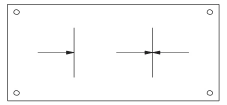
Figure 5—Typical Identification Plate for a Valve with One Seat
Unidirectional and One Seat Bidirectional
NOTE In Figure 5, one symbol indicates the bidirectional seat and the other symbol indicates the unidirectional seat.