API 6D Valve Design Requirements
Design requirement of API 6D Valve covering axial valve, floating ball valve, trunnion ball valve, gate valve and plug valves.
5 Design
5.1 General
5.1.1 Design Standards and Calculations
Design and calculations for pressure-containing parts and pressure boundary bolting shall conform to an internationally recognized design code or standard such as ASME BPVC, Section VIII, Division 1, or Division 2; ASME 16.34; EN 12516- 1 or EN 12516-2; and EN 13445-3.
NOTE 1 See K.4 for use of specific designs codes.
The allowable stress values shall be consistent with the selected design code or standard.
If the selected design code or standard specifies a test pressure, less than 1.5 times the design pressure, then the design pressure for the body calculation shall be increased such that the hydrostatic test pressure in 10.3 and I.5 can be applied.
Pressure containing parts shall include bodies, external trunnions, end connectors, bonnets/covers, and stems/external shaft.
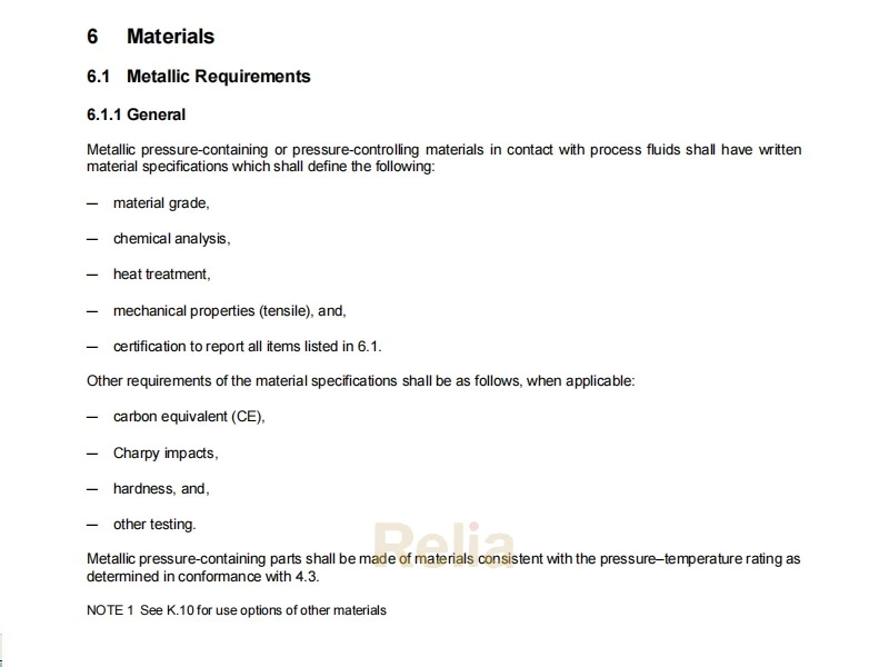
5.1.2 Pressure-containing Parts
Pressure-containing parts shall be designed with materials specified in Section 6.
Pressure boundary bolting shall be designed with materials specified in Section 8.
Pressure containing parts shall include bodies, external trunnions, end connectors, bonnets/covers, and stems/external shaft.
5.1.3 Pressure-controlling Parts
Pressure controlling parts shall include the closure member (ball, disc, plug, gate) and seat.
Design and calculations for pressure-controlling parts shall conform to a documented internationally recognized design code or standard.
5.2 Dimensions
5.2.1 Face-to-face and End-to-end Dimensions
Face-to-face (A) and end-to-end (C) dimensions of valves shall conform to the applicable tables in Annex C.
Weld end-to-end (B) dimensions of valves shall conform to the applicable tables in Annex C.
Face-to-face and end-to-end dimensions for valve sizes not specified in Annex C shall conform to ASME B16.10.
NOTE See Figure B.1 to Figure B.15 reference to dimension A, dimension Band dimension C where shown.
5.2.2 Non-standard Face-to-face and End-t o-end Dimensions
Non-standard face-to face and end-to-end dimensions shall conform to K.5. Non-standard dimensions shall include face-to-face and end-to-end dimensions not shown or not conforming to the values in tables in Annex C or ASME B16.10
If the end-to-end dimension includes the pup pipes/transition pieces, then the pup pipes/transition piece shall conform to all requirements of this standard.
The length of valves having one welding end and one flanged end shall be determined by adding half the length of a flanged-end valve to half the length of a welding-end valve.
Tolerances on the face-to-face and end-to-end dimensions shall be ±0.06 in. (±1.5 mm) for valve sizes NPS 10 (DN 250) and smaller, and ±0.12 in. (±3.0 mm) for valve sizes NPS 12 (DN 300) and larger. Delete this sketch below
NOTE Support legs on some valve designs may extend beyond the end-to-end dimensions to assure that the valve can be safely supported.
5.2.3 End Connectors
5.2.3.1 Flanged Connectors
5.2.3.1.1 General
Flanges shall be furnished with a raised face or ring joint face (raised face or full face). Specified dimensions, tolerances, and finishes, including drilling templates, flange facing, nut-bearing surfaces (i.e. spot facing and back facing), outside diameters, and thickness (see Figure 1) shall conform to:
― ASME B16.5 for sizes up to and including NPS 24 (DN 600).
― ASME B16.47, Series A for NPS 26 (DN 650) and larger sizes.
― MS-SP-44 for sizes NPS 12 (DN 300) to NPS 60 (DN 1500).
NOTE See K.6 for optional requirements for end connectors.
When required, valve end flanges shall be provided with tapped holes for engaging flange bolting.
Thread engagement in a flange with tapped holes shall provide full effective thread engagement, not including the chamfered thread, for a length at least equal to the nominal diameter of the bolt thread.
5.2.3.1.2 Offset of Aligned Flange Centerlines — Lateral Alignment
For valves up to and including NPS 4 (DN 100), the maximum flange misalignment shall be 0.079 in. (2 mm) For valves larger than NPS 4 (DN 100), the maximum flange misalignment shall be 0.118 in. (3 mm).
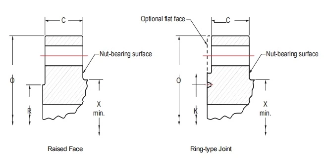
Key
C flange thickness
O outside diameter of flange
R raised-face diameter
K minimum diameter of raised portion of ring type joint flange
X min hub diameter
Figure 1— Typical Flange Dimensions
5.2.3.1.3 Parallelism of Aligned Flange Faces — Angular Alignment
The maximum measured difference between flanges shall be 0.03 in./ft (2.5 mm/m).
5.2.3.1.4 Misalignment of Bolt Holes
For valve end connectors, bolt-hole misalignment of the flange from one end of the valve to the other (see Figure 2) shall conform to the following:
— For valves NPS 4 (DN 100) and small, the misalignment shall not exceed 0,06 in. (1.5 mm) at the bolt holes
— For valves larger than NPS 4 (DN 100), the misalignment shall not exceed 0.12 in. (3.0 mm) at the bolt holes
The surface of the nut bearing area at the back face of flanged valves shall be parallel to within 1° of the flange face.
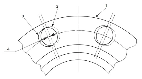
Key
1 flange
2 hole in first flange
3 hole in opposite flange for alignment
A bolt-hole misalignment (see 5.2.3.1.4)
Figure 2— Bolt - hole Misalignment of Flange Across Valve
5.2.3.2 Weld-end Connectors
Weld-end dimensions shall conform to ASME B31.4 or ASME B31.8 or ASME B16.25.
NOTE In the case of a heavy-wall valve body (thicker than the mating pipe), the outside profile may be tapered at 30° and then to 45° as illustrated in ASME B16.25.
The following shall be specified:
— outside diameter,
— wall thickness,
— material grade,
— specified minimum yield strength (SMYS),
— any special chemistry of the mating pipe, and
— if weld overlay has been applied.
NOTE See K.6 for optional requirements for weld end requirements.
5.3 Drive Train
5.3.1 General
The drive train including the stem shall be designed such that the weakest point is outside the pressure boundary.
The valve design shall incorporate features to mitigate the likelihood of misalignment or deflection of the valve stem.
NOTE The weight of the operator and associated drive train components may adversely affect the alignment and deflection of the valve stem.
5.3.2 Torque/Thrust
5.3.2.1 Axial , Floating and Trunnion Ball , Gate or Plug Valves
For axial, floating ball, trunnion mounted ball valve, gate and plug valves, the design thrust or torque for all drive train calculations shall be at least 2.0 times the calculated breakaway thrust or torque.
5.3.2.2 Rising Stem Ball Valves
For torque-seated rising stem ball valves, the design thrust or torque for all drive train calculations shall be at least 1.5 times the calculated breakaway thrust, or torque associated with the non-preferred sealing side and at least 2.0 times the calculated breakaway thrust or torque in the preferred sealing side.
5.3.3 Allowable Stress
Design stresses for tensile stress, shear stress (including torsional shear stress) and bearing stress shall conform to ASME BPVC, Section VIII, Div.1, except that the design stress intensity value, Sm, shall be limited to 67 % of yield strength Syfor the design conditions.
The average primary shear stress across a section loaded under design conditions in pure shear (e.g., keys, shear rings, screw threads, etc.) shall be limited to 0.6Sm .
The maximum primary shear under design conditions, exclusive of stress concentration at the periphery of a solid circular section in torsion, shall be limited to 0.8Sm.
Unless otherwise agreed, the design stress intensity limits shall not apply to the components of rolling-element or other proprietary bearings or high bearing strength capable materials that are included in the drive train where manufacturer's recommendations or limits derived from tests and service experience apply. These limits shall be justified in design documents.
The average bearing stress under the maximum design load shall be limited to the yield strength Sy at temperature.
NOTE The possibility of a shear failure may exist, when bearing loads are applied on parts having free edges, such as at a protruding edge or a keyway.
When mechanical properties at maximum design temperature are not available, a yield test shall be performed at maximum design temperature, or higher, to document the yield strength at maximum design temperature. In order to establish pressure-temperature ratings, the allowable stress shall be based on the yield strength at ambient temperature and the elevated test temperature.
A joint efficiency factor of 0.75 shall be used for fillet welds.
5.3.4 Allowable Deflections
Deflections of the extended drive train shall not prevent the closure member from reaching the fully closed or fully open position.
For all valves, attention shall be paid to deflection and strain.
NOTE Adherence to the allowable stress limits of design codes alone might not result in a functionally acceptable design.
The manufacturer shall demonstrate, by calculation or test, that under loads resulting from design pressure and any defined pipe or external loads, distortion of the closure member or seat does not impair functionality or sealing.
5.3.5 Drive Train Bolting for Quarter-turn Valves
Drive train bolting for quarter-turn valves shall not be subjected to direct shear.
5.4 Operations
5.4.1 Method of Operation
Method of operation (lever, gearbox, or actuator) shall be specified.
When a gear box is provided, the gearbox output torque rating shall be at least 1.5 times the maximum required operating torque of the valve.
Rotary motion to close a valve shall be clockwise.
NOTE Valve operational data may be supplied to the purchaser. See L.2 for options related to valve operational data.
5.4.2 Wrenches (Levers) and Hand-wheels
5.4.2.1 Torque and Size
Wrenches (levers) for valves shall either be of an integral design or consist of a head that fits on the stem and is designed to take an extended handle.
Wrenches (levers) shall not be longer than twice the face-to-face or end-to-end dimension of the valve.
Hand-wheel diameter(s) shall not exceed 40 in. (1 m). Spokes shall not extend beyond the perimeter of the hand- wheel.
The maximum force required at the hand-wheel or wrench(lever) to apply the breakaway torque or thrust shall not exceed 80 lbf (360 N) when applied against MAOP.
5.4.2.2 Extended Stem and Sh aft Assemblies
NOTE Extended stems and shaft assemblies may be provided. See L4 for options related to extended stems and shaft assemblies.
5.4.3 Position Indicators
Except for check valves, the position of the closure member shall not be altered by dynamic forces of the passing flow or in the case of screw operated gate valves by forces generated from internal pressure.
Valves fitted with an actuator or gearbox shall be furnished with a visible indicator to show the open and the closed position of the closure member.
For plug and ball valves, the wrench and/or the position indicator shall be in line with the pipe when the valve is open and transverse when the valve is closed. The design shall be such that the component(s) of the indicator and/or wrench cannot be assembled to falsely indicate the valve position.
When the valve stem is provided with a key slot or master spline in plug or ball valves, the key/master spline shall be in line with the plug/ball bore.
Valves without position stops shall have provision for the verification of open and closed alignment with the operator/ actuator removed.
5.4.4 Travel Stops
Valves that do not require mechanical force to affect a seal shall be provided with travel stops on the valve and/or operator and they shall locate the position of the closure member in the open and closed position. The travel stops shall not affect the sealing capability of the valve.
NOTE See Annex D for guidance for travel stops by valve type.
5.4.5 Actuators
5.4.5.1 General
Actuators and mounting kits shall conform to API 6DX.
5.4.5.2 Alignment
Valve design shall minimize misalignment or improper assembly of components.
NOTE Misalignment or improper assembly of components may be prevented by means of a dowel pin or fitting bolt, which ensures the correct location of operator and stem extension assemblies.
5.4.5.3 Sealing
The design of the interface between operator or enclosed stem extension and the valve shall be sealed to prevent ingress of external contaminants and moisture.
5.4.5.4 Overpressure Protection
Operators and enclosed stem extension assemblies shall be provided with a means of preventing pressure buildup in the mechanism resulting from stem or bonnet seal leakage.
5.5 Cavity Pressure Relief
The manufacturer shall determine whether fluid becomes trapped in the body cavity in the open- and/or closed- valve position.
If liquid or multi-phase fluid trapping is possible, the valve shall be provided with automatic cavity-pressure relief. For gas service for design temperature above 250 °F (121 °C) the manufacturer shall determine the need for cavity relief.
For design temperature up to 250 °F (121 °C) the valve cavity relief shall not exceed 33% differential pressure above the valve pressure rating.
Relief pressures for design temperatures above 250°F (121°C) shall be specified by the manufacturer. To achieve a higher cavity relief pressure, the valve shell shall be designed and tested to withstand a higher hydrostatic shell test pressure. The hydrostatic shell test shall conform to 10.3.
External cavity relief valves shall be NPS ½ (DN 15) or larger.
NOTE 1 If a relief valve fitted to the cavity is required, purchaser may specify provisions to facilitate in service testing.
NOTE 2 Cavity relief testing and functionality may be demonstrated by tests in I.9.2 for trunnion mounted ball valves and gate valves.
5.6 Body Penetrations
5.6.1 Drains
All upstream seated valves shall be equipped with a drain connector.
If threaded, tapered threads shall be capable of providing a seal and shall conform to ASME B1.20.1.
If parallel threads are used, the connector shall have a head section for trapping and retaining a sealing member suitable for the specified valve service. Parallel threads shall conform to ASME B1.20.1 or ISO 228-1.
The drain size shall conform to Table 3.
Table 3―Sizes for Drain
| Nominal Size of Valve (Full or Reduced Bore) | Minimum Pipe Thread/pipe Size* in. (mm) |
Threaded Connector* |
|
| NPS | DN | ||
| ½ to 1½ | 15 to 40 | ¼ (8) | Tapered or Parallel |
| 2 to 8 | 50 to 200 | ½ (15) | Tapered or Parallel |
| 10 and larger | 250 and larger | 1 (25) | Tapered or Parallel |
| FOOTNOTE *The purchaser may specify other sizes and connector types at the time of contract in conformance with K.7 |
|||
5.6.2 Injection Points
Injection fittings shall have a design pressure not less than the greater of the rated pressure or the injection pressure.
Injection points shall incorporate a check valve and a secondary means of isolation for each injection point. Sealant fittings shall have a design pressure not less than the greater of the pipeline valve-rated pressure and the injection pressure.
When provided:
― Seat injection points shall have two non-return valves where one of the non-return valves shall be placed in the valve independent of the outer injection fitting.
― Injection fittings shall incorporate a standard or giant button head connector that is protected by a threaded
cap. This requirement shall not apply to lubricated plug valves.
― Protective caps shall:
― seal-off the button head connector by plugging the sealant port.
― allow any entrapped pressure to be released by the provision of a vent hole.
― Emergency stem/shaft sealant injection points shall be located above the primary sealing barrier, and shall include a button head fitting inclusive of a non-return valve and a protective cap.
― Injector fittings of injectable packing points shall include a non-return valve and plunger.
5.7 Stem Retention
Valves shall be designed to ensure that the stem is retained by pressure-containing parts and pressure boundary bolting and the stem does not eject from internal pressure, under any operating condition or if the packing gland components and/or valve operator mounting components are removed.
5.8 Antistatic
Ball, gate and plug valves shall have electrical resistance not to exceed 10Ω .
NOTE See L.8 for optional testing of electrical resistance.
5.9 Lifting
The manufacturer shall develop lifting sketches and handling instructions (see 14.2.1) for safe lifting operations for valves weighing greater than 55lbs (25kg). The safe working limit (SWL) on any lifting points shall be specified in the lifting sketches and handling instructions.
The manufacturer shall determine the need for and verify suitability of lifting points of the valve.
Valves shall be marked to indicate the SWL of each lifting point
NOTE 1 Regulatory requirements may specify special design, manufacturing, and certification for lifting points.
NOTE 2 For design guidance on lifting lugs, see ASME BTH-1 (Service class 0) or API 17D.
NOTE 3 See K.8 for additional requirements for lifting points.
5.10 Design Process
5.10.1 Design Documentation
Documentation of designs shall include methods, assumptions, calculations, and design requirements.
Design requirements shall include, but not be limited to, those criteria for size, test and operating pressures, material, environmental, and other pertinent requirements on which the design is based.
Design documentation media shall be clear, legible, reproducible, and retrievable. Design documentation shall be retained for 5 years after the last unit of that model, size, and rated working pressure is manufactured.
5.10.2 Design Review and Verification
Design documentation shall be reviewed and verified by any qualified individual other than the individual who created the original design.
5.10.3 Design Validation
Manufacturers shall document their design validation procedures and the results of design validation.
NOTE See K.9 for additional design validation options.