API 6D Scope
API 6D specification defines the requirements for the design, manufacturing, materials, welding, quality control, assembly, testing, marking, documentation and process controls of axial, ball, check, gate, plug valves for application in the petroleum and natural gas industries.
API 6D specification is not applicable to valves for pressure Class 400 and pressure ratings exceeding Class 2500.
API 6DR for repair and remanufacture of valves has been withdrawn and is replaced by Annex A.
Annexes A, B, D, E, and F are informative and contain optional requirements used in this specification.
Annexes C, G, H, I, J, K and L are normative and are mandatory in the use of this specification, when applicable.
Information marked “NOTE” are not requirements but are provided for guidance in understanding or clarifying the associated requirement.
4 APPLICATION, CONFIGURATION and PERFORMANCE
4.1 Valve Types
4.1.1 General
This Specification shall apply to the following:
― axial valves
― ball valves
― check valves
― gate valves
― plug valves
NOTE The nomenclature used in this Specification for typical equipment is shown in Figure B.1 thru B.15.
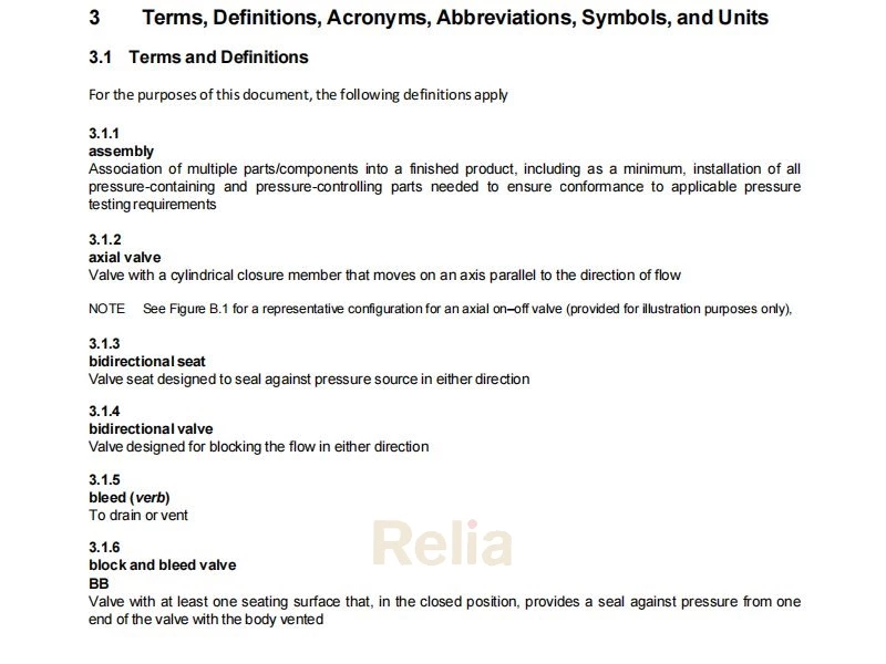
4.1.2 Axial Valves
Axial valves shall have a cylindrical closure member that moves on an axis parallel to the direction of flow.
NOTE A typical configuration for axial valves with flanged or welding ends is shown, for illustration purposes only, in Figure B.1.
4.1.3 Ball Valves
Ball valves shall be of solid one-piece spherical construction with a closure member that rotates on an axis perpendicular to the direction of flow.
NOTE Typical configurations for ball valves with flanged or welding ends are shown, for illustration purposes only, in Figure B.2, Figure B.3, Figure B.4, and Figure B.5.
4.1.4 Check Valves
Check valves shall have a closure member that responds automatically to block fluid in one direction.
NOTE 1 Typical configurations for check valves are shown, for illustration purposes only, in Figure B.6, Figure B.7, Figure B.8, Figure B.9, Figure B.10, Figure B.11 and Figure B.12.
NOTE 2 Check valves can be of the wafer, axial flow, and lift type.
4.1.5 Gate Valves
Gate valves shall have a closure member that moves in a plane perpendicular to the direction of flow.
NOTE 1 The closure member can be constructed of one piece (slab-gate valve) or of two or more pieces (expanding-gate valve).
Gate valves shall be provided with a back seat or secondary stem sealing feature in addition to the primary stem seal.
NOTE 2 Typical configurations for gate valves with flanged and welding ends are shown, for illustration purposes only, in Figure B.13 and Figure B.14.
4.1.6 Plug Valves (Lubricated and Non-l ubricated)
Plug valves shall have a cylindrical or conical closure member that rotates about an axis perpendicular to the direction of flow.
NOTE Atypical configuration for a plug valves with flanged and welding ends is shown, for illustration purposes only, in Figure B.15.
4.2 Conformance and General Performance Requirements
The manufacturer shall conform to all the applicable requirements of this specification.
An internationally recognized quality management system (such as APIQ1 or ISO 9001) shall be applied to assist conformance with the requirements of this specification. The manufacturer shall conform to the requirements of the applicable quality management system.
The purchaser shall be permitted to make any investigation necessary in order to be assured of conformance by the manufacturer and to reject any material or product that does not conform.
Designs shall be validated in conformance with manufacturer’s written specifications.
NOTE 1 Annex F provides design validation criteria that may be used for equipment provided in the as shipped condition.
Additional quality specification levels of Annex I shall apply when specified.
NOTE 2 Annex I identify supplemental requirements for nondestructive examinations and pressure testing that may be performed on a valve when specified by the manufacturer or purchaser. Unless specified in accordance with the allowances in Annex I, only testing and NDE requirements identified in Section 4 through Section 14 apply to valves manufactured to this specification.
The acceptable deviations to minimum specified requirements of Annex K shall apply when specified
NOTE 3 Annex K identifies allowable modifications to specific requirements in Section 4 through Section 14 that may be applied to valves when specified by the purchaser. Valves manufactured with any allowed modification in accordance with Annex K conform to this specification. Unless otherwise specified in accordance with the allowances in Annex K, applicable requirements as stated in Section 4 through Section 14 apply to valves manufactured to this specification without modification.
The supplemental requirements in Annex L shall apply when specified
NOTE 4 Annex L identifies allowable additions or supplements over the requirements in Section 4 through Section 14 that may be applied to valves when specified by the purchaser. Valves manufactured with any allowed addition or supplement in accordance with Annex L conform to this specification.
4.3 Pressure and Temperature Rating
4.3.1 Standard Valves
Valves covered by this specification shall be furnished in one of the following pressure classes (see 3.1.36):
― Class 150
― Class 300
― Class 600
― Class 900
― Class 1500
― Class 2500
Pressure–temperature ratings for class-rated valves shall conform to the rating table for the applicable material group per ASME B16.34 or for carbon steel per MSS-SP 44.
The pressure–temperature rating applied shall be based on the material group of the valve end connector. Where the valve ends are made from material in two different groups, the material with the lower pressure–temperature
rating shall determine the rating.
NOTE Different material or material forms may be used for body and bonnet or cover parts within the same valve.
All metallic pressure-containing and pressure-controlling parts shall be designed to meet the identified valve pressure–temperature rating.
The manufacturer shall determine any limits on the maximum allowable operating pressure and shall identify the minimum and maximum design temperatures resulting from the nonmetallic parts used.
4.3.2 Non-standard Valves— Intermediate Pressures and Temperatures
Intermediate pressure and temperature ratings shall conform to K.2.
NOTE Intermediate pressure and temperature rating cannot apply to valve designs with ASME flanged ends (see K.2)
Pressure–temperature ratings for valves made from materials not listed in ASME B16.34 shall be determined using the methods defined in ASME B16.34 Appendix B up to the temperature limitation of the valve.
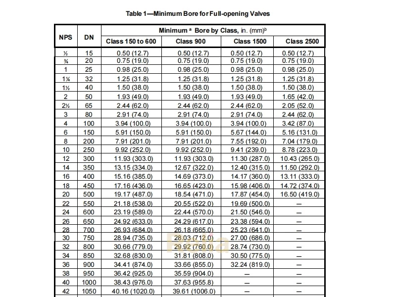
4.4 Nominal Size
Valves manufactured to this specification shall be provided either:
— in nominal sizes as listed in Table 1, or
— in a size and bore determined by agreement when no size or minimum bore dimension is listed in Table 1,
NOTE Welding-end valves may require a smaller bore at the welding end to mate with the pipe.