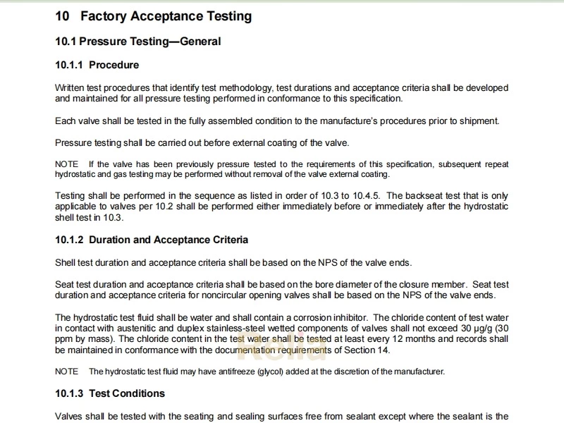
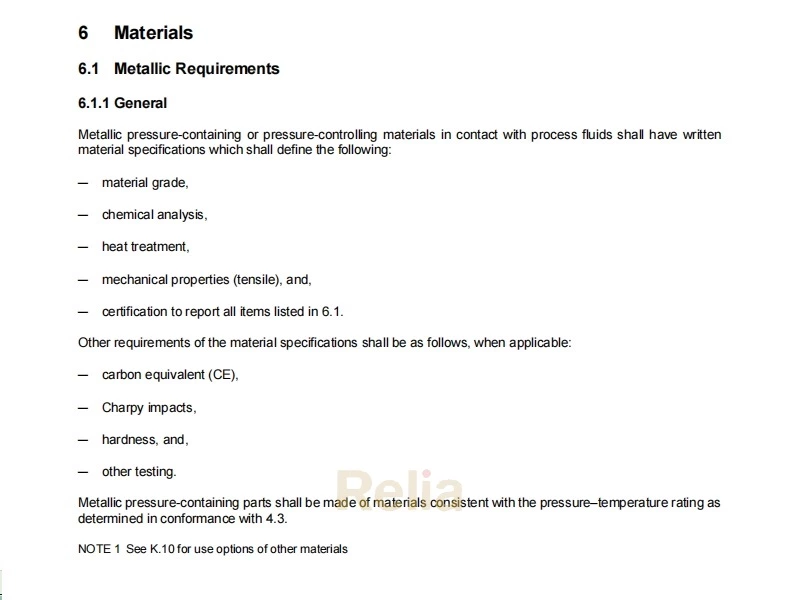
API 6D Quality Control Specifications
API 6D quality control specifies measuring and test equipment, visual examination personnel, welding inspectors, visual inspection, age control and storage for nonmetallic seals, and valve assembly.
9 Quality Control
9.1 Measuring and Test Equipment
9.1.1 Control
Equipment used to inspect, test, or examine material or other equipment used for acceptance shall be identified, controlled, calibrated, and adjusted at specified intervals. Equipment shall be maintained in conformance with documented instructions consistent with nationally or internationally recognized standards.
Calibration intervals shall be established by the valve manufacturer for calibrations based on repeatability and degree of usage.
9.1.2 Dimension-measuring Equipment
Dimension-measuring equipment shall be controlled and calibrated in conformance with methods specified in documented procedures.
9.1.3 Pressure-measuring Devices
9.1.3.1 Type and Accuracy
Test pressure-measuring devices shall be accurate to at least ± 2.0 % of full scale. If analog pressure gauges are used in lieu of pressure transducers, they shall be selected such that the test pressure is indicated within 20 % and 80 % of the full-scale value.
NOTE Pressure recording devices are outside the scope of 9.1.3.1 .
9.1.3.2 Procedure
Pressure-measuring devices shall be calibrated with a master pressure-measuring device or deadweight tester to at least three equidistant points of full scale (excluding zero and full scale as required points of calibration).
NOTE If the number of calibration points is x and the full-scale pressure is Pfs, the intervals between calibration points would be Pfs/(x +1). In terms of % of full scale, the intervals between calibration points would be (100 %) / (x + 1).
EXAMPLE 1 For the minimum requirement of three calibration points, x = 3, and the calibration intervals would be (100 %)/ (3 + 1) = (100 %)/4 = 25 %. As a result, calibration would be performed at 25 %, 50 %, and 75 % of full scale as a minimum.
EXAMPLE 2 For a requirement of five calibration points including full scale, x = 4, because the full-scale calibration is not included in x. The calibration intervals then would be (100 %)/(4 + 1) = (100 %)/5 = 20 %. Therefore, calibration would be performed at 20 %, 40 %, 60 %, 80 %, and 100 % of full scale.
9.1.3.3 Intervals
Calibration intervals shall be established based on repeatability and degree of usage.
The initial interval between calibrations shall be a maximum of 90 days until recorded calibration history can be established by the manufacturer. Increases to the interval between calibrations shall be limited to 90-day increments, with a maximum calibration interval between calibrations to not exceed 1 year.
Calibration intervals shall be adjusted based on review of the recorded calibration history and determination of interval adjustments shall be defined in the manufacturer’s written procedure.
The calibration interval shall start either on the date of calibration or on the date of first use within 90 days of calibration.
If manufacturer chooses to start the calibration interval other than on the date of calibration, the following shall apply:
— the date of first use shall be recorded, and
— the time between the calibration date and date of first use shall not exceed 90 days.
9.2 Visual Examination Personnel
Welding, quality control, pressure testing and machining personnel performing visual inspection for final acceptance shall undergo an annual vision examination in conformance with the manufacturer’s documented procedures that satisfy the applicable requirements of ASNT SNT- TC- 1A or ISO 9712.
NOTE Alternative standards are acceptable provided they meet the minimum requirements of ASNT SNT-TC-1A.
9.3 Welding Inspectors
Personnel performing visual inspections of welding operations and completed welds shall be qualified and recorded in conformance with the manufacturer’s documented procedures.
9.4 Visual Inspection
9.4.1 Visual Inspection of Castings
Visual inspection of all pressure-containing and pressure-controlling steel castings as a minimum shall conform to MSS SP-55. The following acceptance criteria shall apply:
― Type 1: none acceptable.
― Type 2 to 12: A and B only.
For cast materials not covered by MSS SP-55, visual inspection and acceptance criteria shall conform to the manufacturer’s documented procedures.
9.4.2 Visual Inspection of Forgings
Visual inspection of all pressure-containing and pressure-controlling steel forgings as a minimum shall conform to ASME BPVC, Section VIII, Div. 1, UF-45, and UF-46. Visible defects such as seams, laps, or folds shall not be allowed.
9.4.3 Visual Inspection of Final Machined Parts
For stems or shafts, trunnion or trunnion/bearing plates, closure members and seat rings, in addition to the requirements of sections 9.4.1 and 9.4.2 the machined areas of pressure-containing and pressure-controlling castings and forgings shall be visually inspected in conformance with the manufacturer’s requirements.
For seals gaskets, seat springs and parts with plating, the parts shall be visually inspected in conformance with the applicable industry material specification.
9.5 Age Control and Storage for Nonmetallic Seals
9.5.1 Age Control
The manufacturer’s written requirements for nonmetallic seals shall include the following minimum provisions:
― batch number;
― cure/mold date;
― shelf-life expiration date.
9.5.2 Storage
The manufacturer's written requirements for nonmetallic seals shall include the following minimum provisions:
― indoor storage;
― maximum temperature not to exceed 120 °F (49 °C);
― protected from direct natural light;
― stored unstressed (see text below);
― stored away from contact with liquids;
― protected from ozone and radiographic damage.
Packaging and storage of elastomeric seals shall not impose tensile or compressive stresses sufficient to cause permanent deformation or other damage.
NOTE 1 Recommendations are typically available from seal manufacturers.
NOTE 2 Where applicable, for a given seal design, rings of large inside diameter and relatively small cross-section may be formed into three equal super imposed loops to avoid creasing or twisting, but it is not possible to achieve this condition by forming just two loops.
9.6 Valve Assembly
Valves shall be assembled per written procedures developed by the manufacturer. The procedure shall include bolt tightening requirements for pressure boundary bolting.
Interfaces between pressure controlling parts shall be assembled free of any sealant, except where the sealant is the primary means of sealing.
When used for assembly of pressure controlling parts, the lubricant shall not exceed viscosity of SAE 10W motor oil or equivalent.
NOTE 1 Other parts such as threads, bearings, sliding parts, etc. may be lubricated for assembly using an appropriate oil or grease.
NOTE 2 For guidance on restriction of assembly lubricant see L.12
