API 6D Annex L
API 6D Annex L specifies supplemental requirements, which shall be performed by the manufacturer when specified by the purchaser at time of order placement.
Annex L
(normative)
Purchaser-specified Customization–Supplemental Options to Specified Design and Manufacturing Requirements
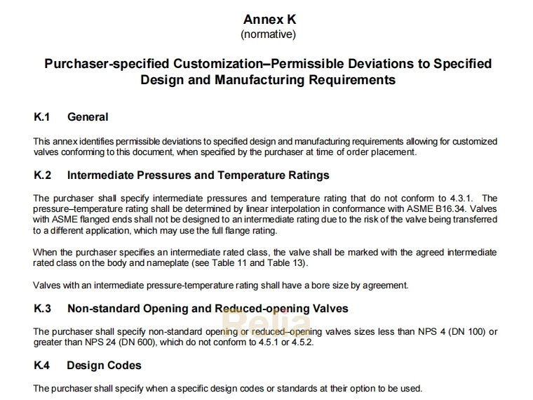
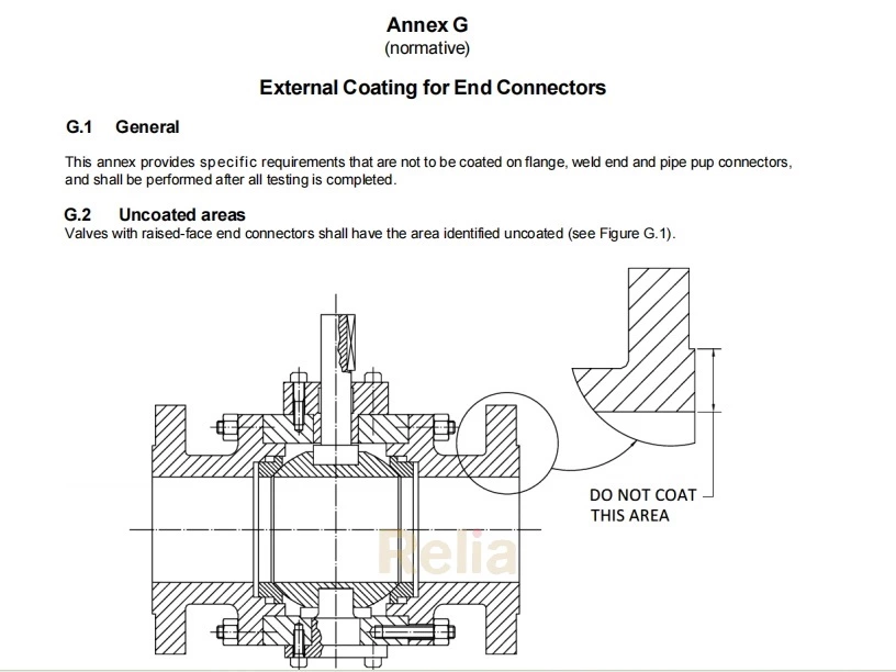
L.1 General
This annex specifies supplemental requirements, which shall be performed by the manufacturer when specified by the purchaser at time of order placement.
L.2 Valve Operational Data
The purchaser shall specify the maximum pressure differential (MPD) when available, at which the valve is required to be opened. If unavailable, the pressure as determined in conformance with 4.3 for material at 100 °F (38 °C) shall be the MPD.
The manufacturer shall provide the following data to the purchaser, when requested:
a) flow coefficient Cv or Kv;
b) Valve top works dimensions (as applicable);
c) Break-to-open torque or thrust (BTO);
d) Break-to-close torque or thrust (BTC);
e) Valve breakaway angle or breakaway percent of stroke;
f) Run-to-open torque or thrust (RTO);
g) Run-to-close (reseat) torque or thrust (RTC);
h) End-to-open torque or thrust (ETO);
i) End-to-close (reseat) torque or thrust (ETC);
j) Valve drive train MAST
k) Length and direction of stroke to open and close for linear valves
l) Angle and direction of rotation for part-turn or check valves
m) Direction of rotation and number of turns for multi-turn valves
n) Thrust necessary to enable valve to maintain position, when applicable
o) Any other specific torque or thrust conditions of the valve
p) Number of cycles expected during the service life of the equipment (end-user provided)
NOTE The breakaway angle or percent of stroke can be significant to actuator sizing when more than 5° or 5 %, respectively.
q) Number of turns for manually operated valves.
Corrosion protection measures for long-term storage or unusual/harsh conditions shall be provided if specified by the purchaser.
L.3 Single Piece Stem
The purchaser shall specify that the stem be constructed from one piece of wrought material.
Welded fabrication or threaded stem assemblies shall not be permitted.
L.4 Extended Stem and Shaft Assemblies for Below Ground Service
The purchaser shall specify when the valve shall be provided with an extended stem. Extended stems and shafts assemblies in below grade (ground level) service shall conform to 5.3 and 5.4. Extended stems and shafts assemblies shall be protected by an extension casing (housing).
The purchaser shall specify when the stem extension shall be permanently attached to the valve.
L.5 Drive Train Strength Test
The purchaser shall specify when the drive train strength test for ball valve, gate valve or plug valves shall be measured. The test torque shall be the greater of:
— two (2) times the manufacturers predicted breakaway torque/thrust; or
— two (2) times the measured breakaway torque/thrust.
The test torque shall be applied with closure member blocked for a minimum time of 1 minute.
NOTE For gate valves, the thrust can be tensile or compressive, whichever is the most stringent condition.
The test shall not cause any permanent visible deformation of the drive train.
For ball and plug valves, the total torsional deflection of the extended drive train when delivering the design torque shall not exceed the overlap contact angle between the seat and closure member.
L.6 Drain, Vent, Sealant Lines
The purchaser shall specify the provision of drain, vent, or sealant lines to be installed on the valve. When provided, drain, vent, and sealant lines shall be composed of rigid pipework. For valve with extended stems, the lines shall be fastened to the valve and/ or extensions.
When provided, drain and vent lines shall:
― have a design pressure not less than the rated pressure of the valve on which they are installed.
― be capable of withstanding the hydrostatic shell test pressure of the valve.
― be designed in conformance with a recognized design code.
― be suitable for blow-down operation, where applicable.
When provided, sealant lines shall be rated to the same criteria as sealant fittings in 5.6
The manufacturer shall recommend the maximum injection pressure for the system.
L.7 Drain, Vent, and Sealant Valves
The purchaser shall specify the provision of drain, vent, or sealant valves to be installed on the valve. When provided, the drain and block valves shall have a rated pressure not less than the valve on which they are installed and be suitable for blow-down operation. Block and check valves fitted to sealant injection lines shall be rated for the greater of the piping valve rated pressure and the injection pressure defined in.5.6
L.8 Antistatic Testing
The purchaser shall specify when the electrical resistance between the closure member and the valve body/bonnet and between the stem/shaft and the valve, body/bonnet shall not exceed 12 V when measured using a direct-current power source. The resistance shall be measured on dry valves before pressure testing and shall not exceed 10 Ω in conformance with 5.8.
L.9 Welding Overlay Iron Dilution
The purchaser shall specify when an iron dilution Class Fe 5 (iron mass fraction 5.0 % maximum) shall be used as part of the CRA weld overlay with nickel-based alloy UNS N06625 as an alternative to 7.5.3.1.
L.10 Corrosion-Resistant Metallic Surfaces
The purchaser shall specify when corrosion-resistant metallic surfaces are required on lip seal or V-packing sealing surfaces.
L.11 Supplemental Hardness Testing—Production Parts for Sour Service
The purchaser shall specify when a production material hardness test on all metallic pressure-containing and pressure-controlling parts for sour service. The maximum hardness shall be as per NACE MR0175/ISO 15156 requirements.
The method of hardness testing shall be performed in accordance with the following:
— For Brinell hardness measurements, testing shall be performed in accordance with ASTM E10 or ISO 6506- 1.
— For Rockwell hardness measurements, testing shall be performed in accordance with ASTM E18 or ISO 6508-1.
— Portable hardness measurements shall be performed in accordance with ASTM E110.
Hardness testing shall not be performed on finished machined parts sealing surfaces.
Results of the production hardness testing shall be reported, and records maintained (see Section 14.1).
NOTE This hardness test may be performed by the supplier on the material provided and reported on the material test report.
L.12 Sour Service for Bolting
The purchaser shall specify when the use of bolting for buried or insulated application shall conform to NACE MR0175/ISO 15156 per 6.5.
L.13 Use of Assembly Lubricant
In conformance with 9.6, purchaser shall specify when no lubricant shall be used on valves during assembly.
L.14 Supplemental Testing—Double Block and Bleed (DBB) Valves
The purchaser shall specify when double block and bleed (DBB) valves shall undergo additional testing. The testing shall be performed as follows:
— With the valve unseated and partially open, the valve and its cavity shall be filled with test fluid.
— The valve shall then be closed, and the valve body vent valve opened to allow excess test fluid to overflow from the valve-cavity test connection.
— The test pressure shall be applied simultaneously from both valve ends.
— Seat tightness shall be monitored via overflow through the valve cavity connection.
— Acceptance criteria shall be per the requirements of 10.4.3, except the metal-to-metal seat test, leakage rate shall not be more than two times ISO 5208, Rate C.
L.15 Supplemental Testing—Double Isolation and Bleed DIB-1 (Both Seats Bidirectional)
The purchaser shall specify when each seat in a double isolation and bleed (DIB- 1) valve shall be tested in both directions. The testing shall be performed as follows:
— Cavity-relief valves shall be removed, if fitted.
— The valve and cavity shall be filled with test fluid, with the valve unseated and partially open, until the test fluid overflows through the cavity relief connectors.
— To test for seat leakage in the direction of the cavity, the valve shall be closed.
— The test pressure shall be applied successively to each valve end to test each seat separately from the upstream side. Leakage shall be monitored via the valve cavity pressure relief connectors.
— Thereafter, each seat shall be tested as a downstream seat. Both ends of the valve shall have the ends open to atmosphere and the valve cavity filled with test fluid.
— Pressure shall then be applied whilst monitoring leakage through each seat at both ends of the valve.
NOTE Some valve types can require the balancing of the upstream and valve cavity pressure during the downstream seat test in which case only one end of the valve shall be open to atmosphere.
— Acceptance criteria shall be per the requirements of 10.4.3, except the metal-to-metal seat test, leakage rate shall not be more than two times ISO 5208, Rate C.
L.16 Supplemental Testing—Double Isolation and Bleed DIB-2 (One Unidirectional and One Bidirectional Seat)
The purchaser shall specify when the bidirectional seat in a double isolation and bleed (DIB-2) valve shall be tested in both directions. The testing shall be performed as follows:
— Cavity-relief valves shall be removed if fitted.
— The valve and cavity shall be filled with test fluid, with the valve unseated and partially half-open, until the test fluid overflows through the cavity relief connectors.
— To test for seat leakage in the direction of the cavity, the valve shall be closed.
— The test pressure shall be applied successively to each valve end to test each seat separately from the upstream side. Leakage shall be monitored via the valve cavity pressure relief connectors.
— To test the bidirectional seat from the cavity test, pressure shall be applied simultaneously to the valve cavity and upstream end. Monitor leakage at the downstream end of the valve.
— Acceptance criteria shall be per the requirements of 10.4.3, except the metal-to-metal seat test, leakage rate shall not be more than two times ISO 5208, Rate C.
L.17 Supplemental FAT
L.17.1 Pressure Testing Valves with Hydrostatic End Load
The purchaser shall specify when valves shall be pressure tested with connectors that subject the valve to hydrostatic end load to the requirements of 10.2, 10.3 and 10.4.
NOTE Visible marks left on the sealing area by the test gasket are acceptable, provided the sealing integrity has been demonstrated.
L.17.2 Low Pressure Gas Seat Testing-Type I (10)
L.17.2.1 Method
The purchaser shall specify when valve shall be seat tested. A Type I test shall be the seat test specified in 10.4 repeated at a test pressure between 5 psi and 14.5 psi (0.34 barg and 1 bar) using air or nitrogen as the test medium.
The closure member and leakage measurement connection port shall be purged with air with valve half open.
Following pressurization and prior to commencing seat leakage measurement, the valve shall be fully stabilized. The valve stabilization period shall not begin until the test pressure in the valve remains constant for at least 2 min.
During the stabilization period, the outlet port from where leakage is to be measured shall remain connected to the leak detection device (e.g. flow meter or water-filled bubble counter vessel) and shall be monitored for the duration.
The stabilization period duration shall not be less than as specified in Table L.1. The duration can be extended in case stabilization is not achieved.
Table L.1—Stabilization Period Duration
| Nominal Pipe Size | Duration (minutes) |
| 4 (DN 100) and below | 5 |
| 6 (DN 150) to 10 (DN 250) | 10 |
| 12 (DN 300) to 18 (DN 450) | 15 |
| 20 (DN 500) and above 30 | 15 |
Following stabilization, the seat leakage test shall begin.
L.17.2.2 Acceptance Criteria
The acceptable leakage rate for low-pressure gas seat testing shall be:
― ISO 5208, Rate A (no visible leakage), for soft-seated valves and lubricated-plug valves; ― ISO 5208, 2 times Rate C, for metal-seated valves, except metal-seated check valves.
― ISO 5208, Rate E, for metal-seated check valves.
L.17.3 Low Pressure Gas Seat Testing -Type II (10)
L.17.3.1 Method
The purchaser shall specify when valve shall be seat tested specified in 10.4 repeated at a test pressure between 80 psi and 100 psi (5.5 bar and 6.9 bar) using air or nitrogen as the test medium.
The valve shall be drained of hydrostatic test fluid and the inner parts shall be fully purged with air prior to the start of the low-pressure gas testing. Pressure shall be considered stabilized when the rate of change is no more than 5% of the test pressure within 5 minutes.
L.17.3.2 Acceptance Criteria
The acceptable leakage rate for low-pressure gas seat testing shall be:
― ISO 5208, Rate A (no visible leakage), for soft-seated valves and lubricated-plug valves; ― ISO 5208, 2 times Rate C, for metal-seated valves, except metal seated check valves.
― ISO 5208, Rate E, for metal-seated check valves.
L.18 Operations Testing—Valves Required Double Isolation and Bleed (DIB)
The purchaser shall specify when valves required for double isolation and bleed (DIB) operations shall be tested. The testing shall be performed as follows:
― Test fluid shall be hydrostatic test fluid that conforms to 10.1.2 or nitrogen gas, as specified.
― The following steps shall be performed on each end or each side of the valve.
Step 1: With valve, partly open, fill valve with test medium and pressurize to valve design pressure.
Step 2: Close valve.
Step 3: Reduce pressure on downstream side of valve to zero and monitor cavity pressure.
Step 4: Monitor leakage between cavity and downstream side.
Step 5: Reduce pressure in cavity slowly, and monitor upstream pressure, and leakage to the downstream side.
Step 6: Reintroduce pressure into the cavity slowly up to 145 psi (10 bar) and monitor leakage to the downstream side.
Step 7: Reduce pressure in cavity slowly and monitor leakage to the downstream side.
Step 8: With cavity and downstream vented to zero, measure upstream seat performance by monitoring leakage at the cavity port.
Step 9: When applicable to the valve type, repeat Steps 1 through 8 on the opposite side of the valve.
― Leakage for soft-seated valves shall not exceed ISO 5208, Rate A; (no visible detectable leakage for the duration of the test at test pressure).
― For metal-seated valves, the leakage rate shall not exceed ISO 5208, Rate C; however, for valves in gas service the leakage rate shall not exceed ISO 5208, Rate D.
L.19 High-pressure Gas Testing
L.19.1 General
The purchaser shall specify when high -pressure gas testing is required.
The valve shall be drained of hydrostatic test fluid and the inner parts shall be fully purged with air prior to the start of the high-pressure gas testing.
L.19.2 High-pressure Gas Shell Test
L.19.2.1 Method
Warning—High-pressure gas testing involves potential hazards. Appropriate safety precautions must be taken.
All gas shell tests specified shall be performed with the valve unseated and partially open and may be performed with the valve fully open, provided the body cavity is simultaneously filled and pressurized through a cavity connection. Test methods used shall be one of the following
― Method 1: Valves shall have a high-pressure gas shell test performed using nitrogen with valve submerged in a water bath during testing or,
― Method 2: Valves shall have a high-pressure gas shell test performed using nitrogen with a 1% - 3 % helium tracer measured using a mass spectrometer.
NOTE By agreement, when the appropriate safety precautions are taken, the high-pressure gas shell test may be performed in a test cell and not submerged in a water bath.
The minimum test pressure shall be 1.1 times the pressure rating determined in conformance with 4.3 for the material at 100 °F (38 °C).
The test duration shall conform to Table L.2.
Table L.2—Minimum Duration of Gas Shell Tests
| Valve Size | Test Duration (minutes) | |
| NPS | DN | |
| ≤ 18 | ≤ 450 | 15 |
| 20 and larger | 500 and larger | 30 |
L.19.2.2 Acceptance Criteria
Acceptance criteria shall satisfy one of the following:
― Method 1: When the valve is tested by submerged method, no visible leakage shall be permitted, or
― Method 2: When using a using a mass spectrometer no visible leakage shall be permitted through any pressure- containing part.
L.19.3 High-pressure Gas Seat Test
L.19.3.1 Method
Valves shall have a high-pressure gas seat test performed using inert gas as the test medium. The minimum test pressure shall be 1.1 times the pressure rating determined in conformance with 4.2 for the material at 100 °F (38 °C).
The test duration shall conform to Table 9.
L.19.3.2 Acceptance Criteria
Leakage for soft-seated valves and lubricated plug valves shall not exceed ISO 5208; Rate A (no visible leakage). For metal-seated valves, except check valves, the leakage rate shall not be more than two times ISO 5208, Rate C.
For metal-seated check valves, the leakage rate shall not exceed ISO 5208, Rate E.
L.20 External Coating or Painting of Corrosion-resistant Valves
The purchaser shall specify when corrosion–resistant valves shall have an external coating or paint system applied.
L.21 Valve Orientation
L.21.1 Operating Orientation
The purchaser shall specify the required operating orientation of the valve when a specific orientation is required for proper operation of the valve in its intended service. When the operating orientation has been specified, the manufacturer shall provide installation, operation, and maintenance instructions for the valve.
L.21.2 Pressure Testing Orientation
The purchaser shall specify the required orientation of the valve during pressure testing when a specific orientation is required for proper operation of the valve in its intended service. The number of valves in a given order that is subject to the required pressure test orientation shall be specified.
L.22 Disassembly/maintenance Tools
The purchaser shall specify when tools shall be supplied for valve designs requiring specialized tools for disassembly or maintenance.
L.23 Pressure Balance Hole
The purchaser shall specify when the closure member in ball or gate valves shall be provided with or without a pressure balance hole.
NOTE Pressure balance hole allows for smaller sized operator and injection of fluids to the main pipeline. Plugging of the hole in fouling service creates the risk of not be able to start or complete the valve stroke in case a small size operator is provided. The absence of a pressure balance hole allows the body cavity to the vented/isolated from the mail pipe in the open position and stem leakage or body leakage will have restricted outflow
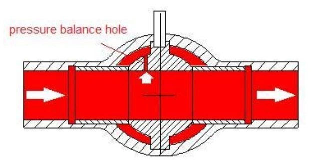
Figure L.1—Pressure Balance Hole for Ball Valve
L.24 Fugitive Emissions
L.24.1 Valve Qualification Testing
The purchaser shall specify when valves shall undergo fugitive emission qualification testing. If specified, qualification testing of valves shall be performed in conformance to a national or international standard such as,
— API 624 for rising stem valves; or,
— API 641 for quarter-turn valves; or,
— ISO 15848- 1 for Industrial valves
NOTE Another methodology may be used to satisfy regulatory or contractual requirements
L.24.2 Valve Production Testing
The purchaser shall specify when valves shall be fugitive emissions production tested. If specified, production fugitive emission testing of valves shall conform to ISO 15848-2
NOTE Another methodology may be used to satisfy regulatory or contractual requirements
L.25 Pigging
The purchaser shall specify the requirements for piggability of the valves.
NOTE 1 Venturi or reduced-bore valves are not suitable for most pigging operations, including intelligent pigging, but can allow the passage of foam pigs.
NOTE 2 A valve in which the drive member or the closure member obstructs the bore in the otherwise fully open position (e.g. a dual- plate check valve) is not piggable.
NOTE 3 Certain full-opening valves with pockets can allow bypass of fluid around a short pig or sphere.
L.26 Locking Provision
The purchaser shall specify when the valves are supplied with a provision for locking. When specified, the locking feature for check valves shall be designed to lock the valve in the open position only. Locking feature for other types of valves shall be designed to lock the valve in the open and/or closed position.
L.27 Service Compatibility
All metallic and nonmetallic parts exposed directly to the pipeline fluid and lubricants shall be compatible for the commissioning fluids and service when specified by the purchaser. Metallic materials pairs shall be selected to have a galling threshold stress above the design compressive load.
Qualification testing of elastomers and thermoplastics shall be performed in accordance with one of the following.
— NORSOK M-710, or
— ISO 23936 Parts 1 and 2, or
— Purchaser-agreed specification
L.28 Fire Testing
The purchaser shall specify when valves shall be qualified by fire testing. If specified, fire tested valves shall be qualified by, testing that conforms to API 6FA or API 607. Testing shall include ancillary valves when specified.
L.29 Radiograph of Pipe Pup Welds
The purchaser shall specify when radiographic testing on 100 % of the weldment shall conform to ASME BPVC, Section V, Article 2. Acceptance shall conform to ASME BPVC, Section VIII, Division 1, UW-51 for linear indications and ASME BPVC, Section VIII, Division 1, Appendix 4 for rounded indications.
The purchaser shall specify when weld ends shall be subjected to surface and /or volumetric NDE.
Volumetric NDE examination of welding ends shall be performed for a minimum length equal to 1.5 times the mating pipe wall thickness or 50 mm, whichever is greater using one of the following, as applicable:
— Radiographic testing on welding ends of castings shall conform to ASME B16.34; Appendix I. Acceptance shall
conform to ASME B16.34, Appendix I.
— Ultrasonic testing on welding ends of castings shall conform to ASME B16.34: Appendix IV. Acceptance shall conform to ASME B16.34, Appendix IV.
— Ultrasonic testing on welding ends of forgings and plate shall conform to ASME B16.34, Appendix IV. Acceptance shall conform to ASME B16.34, Appendix IV.
Surface NDE shall be performed on the machined ends of the valve-weld bevel using one of the following:
— Magnetic particle testing on weld bevels of weld ends after machining shall conform to ASME BPVC, Section V, Article 7. Acceptance shall conform to ASME BPVC, Section VIII, Division 1, Appendix 6.
— Penetrant testing on weld bevels of weld ends after machining shall conform to ASME BPVC, Section V, Article 6. Acceptance shall conform to ASME BPVC, Section VIII, Division 1, Appendix 8.