API 6D Annex I
API 6D Annex I specifies the requirements for NDE, documentation and pressure testing and other supplemental requirements that shall be performed by the valve manufacturer when specified by the customer.
API 6D Annex I
(normative)
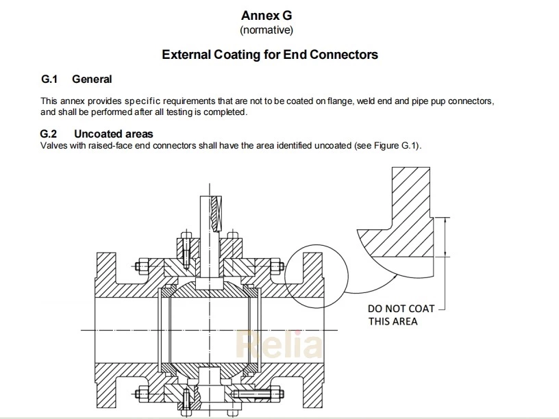
Quality Specification Level (QSL)
I.1 General
This annex specifies the requirements for NDE, documentation and pressure testing and other supplemental requirements that shall be performed by the manufacturer when specified by the customer.
The QSL requirements of this annex shall apply in lieu of the equivalent NDE, pressure testing and documentation requirements from the main body of this specification.
NOTE The QSLs increase in stringency of requirements with the QSL numbers 2, 3, 3G, 4 and 4G.
Since some QSL requirements affect material processing, the QSL shall apply only when specified at the time of order placement. When any of the QSLs are specified, all requirements of a specific QSL shall apply.
I.2 NDE requirements for Quality Specification Levels
The requirements of Table I.1 shall apply for NDE requirements for metallic parts for QSL2, QSL3/3G and QSL4/4G.
NOTE 1 The requirements of Table I.1 vary by the type of raw material for the item being inspected.
The requirements of Table I.2 shall apply to the extent, method, and acceptance criteria for the various inspection codes used in Table I.1.
NDE personnel shall be qualified in conformance with the manufacturer’s documented training program that is based on the requirements specified in ASNT SNT-TC-1A or ACCP-CP-1 or ISO 9712.
A qualified Level III examiner that conforms to the requirements of ASNT SNT-TC- 1A or ACCP-CP-1 or ISO 9712 shall approve all NDE procedures.
Minimum NDE Level 2 personnel shall perform all NDE inspection activities for interpretation of acceptance criteria.
NOTE 2 For use of outsourced qualification of Nondestructive Examination (NDE) Services, see API 20D.
Table I.1—NDE Requirements (see Note 1)
| Part | QSL2 | QSL3/3G | QSL4/4G | |||||
| Cast | Wrought g | Cast | Wrought g | Cast | Wrought g | |||
| Body or closures and end connectors or bonnet or cover or gland housing |
QSL2 | QSL3/3G | QSL4/4G | |||||
| VT1 | VT2 | VT1 | VT2 | VT1 | VT2 | |||
| MT2 or PT2 | MT1 or PT1 | MT2 or PT2 | MT1 or PT1 | MT2 or PT2 | MT1 or PT1 | |||
| - | - | RT1 a | UT2 | RT1 and UT1 a f | UT2 | |||
| Welding ends b | MT2 or PT2 | MT1 or PT1 | MT2 or PT2 | MT1 or PT1 | MT2 or PT2 | MT1 or PT1 | ||
| RT3 or UT4 | UT2 | RT3 or UT4 | UT2 | RT3 or UT4 | UT2 | |||
| Stem or shaft c | - | VT5 | - | MT1 or PT1 | - | MT1 or PT1 | ||
| - | - | - | - | - | UT2 | |||
| Trunnion d or Trunnion/bearing plates | VT1 and VT5 | VT2 and VT5 | VT1 | VT2 | VT1 | - | ||
| MT2 or PT2 | MT1 or PT1 | MT2 or PT2 | MT1 or PT1 | |||||
| UT1 | UT2 | |||||||
| Pressure boundary bolting | Table I.3 | Table I.3 | ||||||
| Closure member c Seat rings c | VT1 and VT5 | VT2 and VT5 | VT1 | VT2 | VT1 | - | ||
| MT2 or PT2 | MT1 or PT1 | MT2 or PT2 | MT1 or PT1 | |||||
| Corrosion-resistant overlay in final supplied condition | VT3 | VT3 | VT3 | VT3 | VT3 | VT3 | ||
| PT1 | PT1 | PT1 | PT1 | PT1 | PT1 | |||
| UT3 | UT3 | |||||||
| Fillet and attachment welds to pressure-containing parts | VT3 | VT3 | VT3 | VT3 | VT3 | VT3 | ||
| MT1 or PT1 | MT1 or PT1 | MT1 or PT1 | MT1 or PT1 | |||||
| Hard facing | VT4 | VT4 | PT1 | PT1 | PT1 | PT1 | ||
| Sealing surfaces | MT3 or PT3 | MT3 or PT3 | MT3 or PT3 | MT3 or PT3 | ||||
| Seal gaskets & Seat springs | VT4 | |||||||
| Pressure-containing welds Pipe pup to valve welds or pipe pups e |
VT3 and MT1 or PT1 and RT2 or UT3 |
|||||||
| Reinforcement & welds stiffening | VT3 | |||||||
| Plating | VT4 | |||||||
FOOTNOTES
NOTE 1 See Table I.2 for specification of the examinations referred to in this table.
a RT1 may be replaced by UT4 by agreement.
b A band around each weld end extending back from the body end a distance equal to the greater of 3tm or 2.75 in. (70 mm) See ASME B16.34 for verification of wall thickness ‘tm’.
c MT or PT to be performed prior to coating, plating, or overlay.
d Trunnion designs may be pressure containing or pressure controlling. If the trunnion is a pressure-containing part, then the requirements for body apply.
e NDE requirements of pipe pups shall be established by agreement.
f RT1 plus UT1 may be replaced by RT3.
g Wrought material applies to Bar, Forgings and Plate.
Table I.2—Extent, Method, and Acceptance Criteria of NDE/Item Examination Code
| Exam | Extent | Method | Acceptance |
| RT1 | Critical areas per ASME B16.34 or as defined by manufacture | ASME BPVC, Section V, Article 2 | ASME BPVC, Section VIII, Division 1, Appendix 7 |
| RT2 | 100 % where practicable | ASME BPVC, Section V, Article 2 | ASME BPVC, Section VIII, Division 1, UW-51 for linear indications and ASME BPVC, Section VIII, Division 1, Appendix 4 for rounded indications |
| RT3 | 100 % | ASME BPVC, Section V, Article 2 | ASME BPVC, Section VIII, Division 1, Appendix 7 |
| UT1 | Remaining areas not covered by RT1 | ASME BPVC, Section V, Article 5 | ASTM A609/A609M, Table 2, Quality Level 2 |
| UT2 | All surfaces | ASME BPVC, Section V, Article 5 | Forgings: ASME BPVC, Section VIII, Div. 1, UF-55 for angle beam and ASME B16.34 for straight beam Plate: ASTM A578/A578M Acceptance standard level B |
| UT3 | Weldments: All surfaces | ASME BPVC, Section V, Article 4 | ASME BPVC, Section VIII, Division 1, Appendix 12 |
| Overlay: All accessible machined surfaces | ASME BPVC, Section V, Article 4 straight beam method | ASTM A578A/A578M standard Level C | |
| UT4 | 100 % | ASME BPVC, Section V, Article 5 | ASTM A609/A609M, Table 2, Quality Level 1 |
| MT1 | All accessible surfaces | ASME BPVC, Section V, Article 7 | ASME BPVC, Section VIII, Division 1, Appendix 6 |
| MT2 | All accessible surfaces | ASME BPVC, Section V, Article 7 | ASME BPVC, Section VIII, Division 1, Appendix 7 |
| MT3 | All sealing surfaces | ASME BPVC, Section V, Article 7 | No relevant rounded or relevant linear indications in pressure-contact sealing surfaces shall be permitted a |
| PT1 | All accessible surfaces | ASME BPVC, Section V, Article 6 | ASME BPVC, Section VIII, Division 1, Appendix 8 |
| PT2 | All accessible surfaces | ASME BPVC, Section V, Article 6 | ASME BPVC, Section VIII, Division 1, Appendix 7 |
| PT3 | All sealing surfaces | ASME BPVC, Section V, Article 7 | No relevant rounded or relevant linear indications in pressure-contact sealing surfaces shall be permitted a |
| VT1 | 100 % accessible as cast surfaces | 9.4 | 9.4 |
| VT2 | 100 % accessible as forged surfaces | ASME BPVC, Section VIII, Div. 1, UF-45, and UF-46 | Visible defects such as seams, laps, or folds are not allowed. |
| VT3 | 100 % accessible as welded surfaces | ASME BPVC, Section V, Article 9 | Undercut shall not reduce the thickness in the area(considering both sides) to below the minimum thickness. Surface porosity and exposed slag are not permitted on or within 45 mm of seating surfaces |
| VT4 | 100 % accessible surfaces | Per applicable industry material specification | Per applicable industry material specification |
| VT5 | 100 % accessible machined surfaces | Visual testing takes into account the requirements of 9.2 | Per applicable manufacturer’s requirements |
FOOTNOTE
a A relevant indication is defined as a surface NDE indication with major dimensions greater than 1.6 mm (1/16 in.). An indication not associated with a surface rupture is not considered to be a relevant indication.
I.3 Production Material Requirements
The production requirements for casting, open die forgings, close dies forgings, alloy and carbon steel bolting and corrosion resistant bolting requirements for QSL-3 and QSL-4 shall conform to Table I.3.
NOTE Use of materials or services that conform to API 20A, API 20B, API 20C, API 20E or API 20F does not require the material or service be provided from a facility that is specifically licensed to API 20A, API 20B, API 20C, API 20E or API 20F, respectively.
Table I.3 — Production Materials Requirements
| Level | Applicable Reference | Applicable BSL-CSL-FSL |
| QSL 2 | PMR | PMR |
| QSL3/3G | API 20A, Section 5 | CSL 2 |
| API 20B, Section 5 | FSL 2 | |
| API 20C, Section 5 | FSL 2 | |
| API 20E, Section 5 a | BSL 2 | |
| API 20F, Section 5 a | BSL 2 | |
| QSL4/4G | API 20A, Section 5 | CSL 3 |
| API 20B, Section 5 | FSL 3 | |
| API 20C, Section 5 | FSL3 | |
| API 20E, Section 5a | BSL 3 | |
| API 20F, Section 5a | BSL 3 |
FOOTNOTE
a A relevant indication is defined as a surface NDE indication with major dimensions greater than 1.6 mm (1/16 in.). An indication not associated with a surface rupture is not considered to be a relevant indication.
I.4 Hydrostatic/Gas Testing Sequence
Hydrostatic/gas testing for QSL2, QSL3, QSL3G, QSL4, and QSL4G shall conform to Table I.4.
Table I.4—Pressure Testing Sequences for Quality Specification Levels
| QSL2 | QSL3 a, b | QSL3G a, b | QSL4 a, b, c | QSL4G a, b, c | |
| Hydrostatic Shell test per 10.3 | One Test | Two Tests | Two Tests | Three Tests | Three Tests |
| Hydrostatic Seat test per 10.4 | One Test | Two Tests | N/R d | Three Tests | N/R d |
| Low Pressure Gas Seat test per I.6.1. Type II | One Test | Two Tests | N/R | Three Tests | N/R |
| High Gas Shell test per I.7.2 | N/R | N/R | Two Tests | N/R | Three Tests |
| High Pressure Gas Seat test per I.7.3 | N/R | N/R | Two Tests | N/R | Three Tests |
| Low Pressure Gas Seat test per I.6.1. Type II | N/R | N/R | Two Tests | N/R | Three Tests |
| Torque or thrust test per I.8 | N/R | All | All | All | All |
| Seat cavity relief test per I.9 | 1 Off | All | All | All | All |
FOOTNOTES
a. For all QSL3, QSL3G, QSL4 and QSL4G shell tests, after each test the pressure shall be reduced to zero.
b. For all QSL3, QSL3G, QSL4 and QSL4G seat tests, after each test the pressure shall be reduced to zero and for actuated valves, the valve shall be cycled fully open to fully closed.
c. For all QSL4 and QSL4G tests, the second pressure test shall have an extended duration of four times (4x).
d. As per manufacturer’s requirement a hydrostatic seat test per 10.4 may be performed.
N/R-indicates “ Not Required”
I.5 Hydrostatic Testing
By agreement, hydrostatic testing shall be performed at pressures higher than specified in 10.3 and 10.4 and/or for periods longer than specified in Table 9, and Table 10 as specified by the purchaser. Hydrostatic test fluid shall conform to 10.1.2.
I.6 Low-pressure Gas Seat Testing
I.6.1 Low Pressure Gas Seat Testing -Type II
The seat shall be tested as specified in 10.4 at a test pressure between 80 psi and 100 psi (5.5 bar and 6.9 bar) using air or nitrogen as the test medium. Pressure shall be identified as stabilized when the rate of change is no more than 5% of the test pressure within 5 minutes.
I.6.2 Acceptance Criteria
The acceptable leakage rate for low-pressure gas seat testing shall be:
― ISO 5208, Rate A (no visible leakage), for soft-seated valves and lubricated-plug valves; ― ISO 5208, 2 times Rate C, for metal-seated valves, except metal seated check valves.
― ISO 5208, Rate E, for metal-seated check valves.
I.7 High-pressure Gas Testing
I.7.1 Valve Preparation for Testing
The valve shall be drained of hydrostatic test fluid and the inner parts shall be fully purged with air prior to the start of the high-pressure gas testing.
I.7.2 High-pressure Gas Shell Test
I.7.2.1 Method
Warning—High-pressure gas testing involves potential hazards. Appropriate safety precautions must be taken.
All gas shell tests specified shall be performed with the valve unseated and partially open and may be performed with the valve fully open, provided the body cavity is simultaneously filled and pressurized through a cavity connection. Test methods used shall be one of the following
― Method 1: Valves shall have a high-pressure gas shell test performed using nitrogen with valve submerged in a water bath during testing or,
― Method 2: Valves shall have a high-pressure gas shell test performed using nitrogen with a 1-3 % helium tracer measured using a mass spectrometer.
NOTE By agreement, when the appropriate safety precautions are taken, the high-pressure gas shell test may be performed in a test cell and not submerged in a water bath.
The minimum test pressure shall be 1.1 times the pressure rating determined in conformance with 4.3 for the material at 100 °F (38 °C).
The test duration shall conform to Table I.5.
Table I.5—Minimum Duration of Gas Shell Tests
| Valve Size | Test Duration minutes | |
| NPS | DN | |
| ≤ 18 | ≤ 450 | 15 |
| 20 and larger | 500 and larger | 30 |
I.7.2.2 Acceptance Criteria
Acceptance criteria shall satisfy one of the following:
― Method 1: When the valve is tested by submerged method, no visible leakage shall be permitted, or
― Method 2: When using a using a mass spectrometer no visible leakage shall be permitted through any pressure- containing part.
I.7.3 High-pressure Gas Seat Test
I.7.3.1 Method
Valves shall have a high-pressure gas seat test performed using inert gas as the test medium. The minimum test pressure shall be 1.1 times the pressure rating determined in conformance with 4.3 for the material at 100 °F (38 °C).
The test duration shall conform to Table 9.
I.7.3.2 Acceptance Criteria
Leakage for soft-seated valves and lubricated plug valves shall not exceed ISO 5208; Rate A (no visible leakage). For metal-seated valves, except check valves, the leakage rate shall not be more than two times ISO 5208, Rate C.
For metal-seated check valves, the leakage rate shall not exceed ISO 5208, Rate E.
I.8 Torque/Thrust Functional Testing
I.8.1 Method
The maximum torque or thrust required to operate axial valve, ball valve, gate valve or plug valves shall be measured at the pressure specified by the purchaser for the following valve operations:
a) Open-to-closed with the bore pressurized and the cavity at atmospheric pressure, when applicable to the valve design
b) Closed-to-open with both sides of the closure member pressurized and the cavity at atmospheric pressure c) Closed-to-open with one side of the closure member pressurized and the cavity at atmospheric pressure
d) as in Item c) but with the other side of the closure member pressurized
Torque or thrust values shall be measured with seats free of sealant except where the sealant is the primary means of sealing. If required for assembly, a lubricant with a viscosity not exceeding that of SAE 10W motor oil or equivalent may be used.
Thrust and torque testing shall be performed following high-pressure hydrostatic seat testing and, if specified, prior to any low-pressure gas seat testing.
I.8.2 Calibration
Calibration of torque/thrust-measuring devices shall be as follows:
― Torque/thrust measuring devices shall be accurate to within ± 2.0 % of the full scale
― Torque/thrust measurements shall be made at between 20 % and 80 % of the full range of the measuring device
― Torque /thrust measuring devices shall be calibrated with a master device to at least three equidistant points of full scale (excluding zero and full scale as required points of calibration)
I.8.3 Acceptance Criteria
The measured torque or thrust results shall be recorded and shall not exceed the manufacturer’s documented breakaway torque/thrust.
I.9 Cavity Relief Testing
I.9.1 General
If the valve has one or more self-relieving seats or a relief system that connects the valve cavity to one side of the valve, the test shall conform to a documented procedure, by agreement.
Each valve shall be tested except valves that cannot trap pressure in the cavity.
For valves where cavity overpressure relief is provided via one or more self- relieving seats, this shall be demonstrated by one of the cavity relief tests in I.9.2 or I.9.3.
For trunnion-mounted ball valves with self-relieving seats, selection of one of the three procedures of in I.9.2 shall be by agreement
I.9.2 Trunnion-mounted Ball Valves
I.9.2.1 Procedure 1— Internal Relieving Seats
The procedure for cavity-relief testing of trunnion-mounted ball valves with internal-relieving seats shall be as follows:
a) Fill the valve in the half-open position with hydrostatic test fluid and purge trapped air
b) Close the valve
c) Close the branch vents
d) Apply pressure to the valve cavity until one branch pressure starts to rise and the seat relieves the cavity pressure into the valve end; record this relief pressure and port location.
For valve types with two self-relieving seats, continue to increase the pressure to the cavity until the second branch pressure starts to rise and the second seat relieves; record the relief pressure of the second seat.
Failure to relieve at differential pressure less than 33 % of the valve pressure rating shall be cause for rejection.
EXAMPLE 1: Class 150, 275 psi (19.0 bar), the maximum rated pressure-relief pressure is 90 psi (6.2 bar).
EXAMPLE 2: Class 2500, 6250 psi (430.9 bar), the maximum rated pressure-relief pressure is 2060 psi (142.1 bar).
Failure to relieve pressure shall be cause for rejection.
Pressure–temperature ratings for class-rated valves shall conform to the applicable rating table for the appropriate material group in ASME B16.34 or MSS-SP 44.
I.9.2.2 Optional Procedure 2—One or More Self-relieving Seats
The procedure for cavity-relief testing of trunnion-mounted ball valves with one or more self-relieving seats shall be conducted using the following.
a) Fill the valve in the half-open position with hydrostatic test fluid.
b) Close the valve.
c) Pressurize both sides of the valve and the valve cavity simultaneously, up to 1.0 times rated working pressure (RWP).
d) Isolate both sides of the valve and the valve cavity from pressure source.
e) Slowly decrease pressure on one side while monitoring the valve cavity pressure. Record pressure on that side required to activate SPE seat seal relief (point at which valve cavity pressure decreases).
f) Repeat Steps a) to d) for the other side if it has a self-relieving seat.
Failure to relieve at a differential pressure less than 33% the valve pressure rating over the valve pressure rating shall be cause for rejection.
Pressure–temperature ratings for class-rated valves shall conform to the applicable rating table for the appropriate material group in ASME B16.34 or MSS-SP 44.
I.9.2.3 Procedure 3— Relief System Connecting Valve Cavity to One Valve Side
The procedure for cavity-relief testing of trunnion-mounted ball valves with a relief system that connects the valve cavity to one side of the valve shall be as follows:
a) Fill the valve in the half-open position with hydrostatic test fluid and purge trapped air
b) Close the valve
c) Close the branch vents
d) Apply pressure to the valve cavity until one branch pressure starts to rise; record this relief pressure and port location
Failure to relieve at differential pressure less than 33 % of the valve pressure rating shall be cause for rejection.
EXAMPLE 1: Class 150, 275 psi (19.0 bar), the maximum rated pressure-relief pressure is 90 psi (6.2 bar).
EXAMPLE 2: Class 2500, 6250 psi (430.9 bar), the maximum rated pressure-relief pressure is 2060 psi (142.1 bar).
I.9.3 Through-conduit Slab Gate Valves with Self-relieving Seats
Slab gate valves with one or more self-relieving seats that are upstream and/or downstream shall internally relieve the excess cavity pressure.
The procedure for cavity-relief testing of through-conduit slab gate valves with internal-relieving seats shall be as follows:
a) Fill the valve in the half-open position with hydrostatic test fluid and purge any trapped air
b) Close the valve (see NOTE 1)
NOTE 1 For through-conduit gate valves with rising stem hydrostatic test fluid volume may need to be adjusted during the closing stroke.
c) Close both branch vents
d) Apply design pressure (or other pressure agreed with the purchaser) via one of the valve branches with the opposite branch vented to atmosphere
e) Apply pressure to the valve cavity until the pressure in the pressurized branch starts to rise and the seat relieves the cavity pressure into the valve end; record this relief pressure
f) Failure to relieve at differential pressure less than 33% of the valve pressure rating over the valve pressure rating shall be cause for rejection
NOTE 2 For downstream sealing through-conduit gate valves, a center cavity pressure port is required.
I.9.4 Floating Ball Valves
I.9.4.1 Procedure 1
NOTE This procedure requires a test port in the valve body to have access to body cavity.
The test should be performed with a hydrostatic test fluid
The procedure shall be as follows:
a) Fill the valve in the half-open position with hydrostatic test fluid and purge trapped air
b) Close the valve
c) Apply pressure to the valve cavity until one branch pressure starts to release and the seat relieves the cavity pressure into the valve end; record this relief pressure and port location
Acceptance criteria shall be that the valve shall relieve at differential pressure less than 33 % of the valve pressure rating.
I.9.4.2 Procedure 2
NOTE This procedure does not require a test port in the valve body.
The test shall be performed with nitrogen
The procedure shall be as follows:
a) With the valve in half-open position, pressurize the valve to the valve pressure rating plus the maximum theoretical cavity relief pressure
b) Isolate the valve from the pressure source
c) Close the ball
d) Vent each end to atmospheric pressure
e) Isolate each end of the valve of the atmospheric pressure
f) Open the valve to the half-open position for the release of trapped pressure in the body cavity
g) Monitor the release pressure into the valve bore (only one pressure gauge can be used and installed)
Acceptance criteria shall be as follows:
— Acceptance criteria of the release pressure shall be defined and calculated considering variation of initial pressure at volume of the valve body cavity (closed position) and final pressure at volume (volume of whole valve body + volume of the isolated test rig portion).
— Monitored release pressure above the calculated criteria shall be cause for rejection.
I.10 Documentation
The manufacturer shall maintain documentation as specified in Table I.6 for equipment that satisfies QSL2, QSL3/3G, and QSL4/4G.
Table I.6— Documentation Requirements for Each QSL
| Item | Documentation | QSL2 | QSL3/3G | QSL4/4G |
| 1 | Certificate of conformance to this Annex and QSL | X | X | X |
| 2 | Pressure test report (including pressure, test duration, test medium, and acceptance criteria) including copy of chart recorder used on pressure test | X | X | X |
| 3 | Calibration certificates on pressure test equipment used (e.g. pressure gauges, transducers, and chart recorders) | N/R | X | X |
| 4 | Heat-treatment records on all pressure containing and pressure controlling parts including times and temperatures, e.g. charts | N/R | X | X |
| 5 | Material test reports on all pressure-containing and pressure-controlling parts | X | X | X |
| 6 | For sour service valves, certificate of conformance to NACE MR0175/ISO 15156 | X | X | X |
| 7 | General arrangements drawings | X | X | X |
| 8 | NDE records | N/R | X | X |
| 9 | Cross-sectional assembly drawings with parts list and materials list including design code for pressure containing parts and pressure boundary bolting | X | X | X |
| 10 | Installation, operation, and maintenance instructions/manuals | X | X | X |
FOOTNOTES
X-Indicates required documentation to be maintained by the manufacturer
N/R-indicates not required