API 6D Annex F
API 6D annex F provides design validation test procedures for equipment identified in this specification, which shall be applied if specified by the manufacturer or purchaser.
Annex F
(informative)
Design Validation Test
F.1 General
This annex provides design validation test procedures for equipment identified in this specification, which shall be applied if specified by the manufacturer or purchaser.
When this annex is applied, the design validation procedures in this annex shall be applied to the designs of products, including design changes. It is intended that this annex shall not apply to validation of components and or parts.
NOTE Additional procedure may be used by agreement, provided the test requirements of this annex are met or exceeded.
F.2 Effect of Changes in Product
F.2.1 Design Changes
A change in one of the following parameters shall require a new design validation:
― valve configuration
― body style (e.g. two-piece versus three-piece, top entry versus side entry)
― type of sealing element (e.g. O-ring, lipseals, chevrons, BX ring, RTJ)
― sizing criteria on pressure-containing parts
― sizing criteria of closure member and seats
― design of seal mating parts
― sizing criteria of seat/closure member interfaces
― sizing criteria of the drive train
― maximum speed of operation (e.g. a valve qualified for a 10-second operation would qualify all slower operating times)
Valve operations during the design validation shall be performed at the qualified speed of operation or faster (e.g. a qualified speed of 10 seconds requires all valve operations to be 10 seconds or less).
Other changes (such as supplier of sealing element and configuration of seat) shall not require new design validation if the manufacturer demonstrates that the performance of the product in the intended pressure, temperature, and service condition shall be maintained.
F.3 Products for Design Validation
F.3.1 General
Design validation shall be performed on full-size prototypes or production unit.
NOTE Valves or components that have undergone validation testing may be used for further testing or in a production unit.
If the qualification valve is to be reassembled and use as production unit after design validation testing is performed, the following minimum activities shall apply:
― all seals replaced, and
― dimensional inspection on pressure-containing and pressure-controlling parts and pressure boundary bolting performed to ensure continued conformance with the manufacturer’s drawing dimensions and design acceptance criteria, and
― sealing surface finishes on pressure-containing and pressure-controlling parts checked to ensure continued conformance with the design acceptance criteria, and
― nonconforming parts reworked or replaced, and
― for reworked components, manufacturer shall demonstrate that the rework does not affect any of the elements or parameters listed in F.2, and
― reapply the same surface NDE already applied on the finished machined components during production for critical parts, and
― production testing is performed.
F.3.2 Testing Product
Design validation shall be performed on full-size qualification units.
For products that are provided with multiple sealing sets, each seal set shall be independently verified at the beginning, at the minimum and maximum temperatures, and at the end of the design validation procedure.
NOTE A chevron packing is considered as a single sealing set.
F.4 External Paint or Coatings
The product used in any pressure test shall be free of paint or other coatings that can impede leak detection and/or leak observation.
F.5 Safety
The manufacturer shall identify and implement the actions needed to ensure the safety of personnel and equipment.
F.6 Test Orientation
Validation test shall be performed with stem in vertical orientation with horizontal bore, unless otherwise agreed
Different installation between prototype and production valve shall not require a new validation test if the suitability of the orientation can be substantiated by other means.
F.7 Pressure Testing
The testing medium shall be a fluid that remains in the liquid or gaseous state throughout the testing temperature.
NOTE Hydrostatic test fluid (see 10.1.2) gas, hydraulic fluid, or other mixtures of fluids may be used as the testing medium.
F.8 Temperature Testing
F.8.1 Location of Temperature Measurement
The temperature shall be measured using one of the following methods:
Method 1—In contact with the external surface on two locations as a minimum:
― in the seat area, and
― on the bonnet adjacent to the stem seal.
Method 2—In contact with the equipment being tested and within 0.5 in. (13 mm) of the surface wetted by the retained fluid.
Method 3—For maximum-temperature measurement only, the temperature of the fluid used for heating can be employed if the part is not artificially cooled.
All temperature readings shall be above the maximum and below minimum testing temperatures, respectively.
F.8.2 Application of Cooling for Minimum Temperature Testing
The cooling for minimum temperature testing shall be applied on the external surface of the equipment and/or through the valve bore, per manufacturer's design criteria.
F.9 Hold Periods
F.9.1 Start of Hold Periods
Hold periods shall start after pressure and temperature stabilization has occurred and the equipment with a pressure-monitoring device has been isolated from the pressure source. The specified hold times shall be a minimum.
F.9.2 Pressure Stabilization
The stabilization criteria shall be documented in the manufacturer’s pressure testing procedure.
F.9.3 Pressure Maintenance
Pressure shall remain within 5% of the test pressure or within 8 psi/min (57.5 KPa/min) whichever is less, during the test hold period. Pressure shall not fall below the test pressure before the end of the test hold period.
F.9.4 Temperature Stabilization
Temperature shall be recognized as stabilized when the rate of change is less than 1 °F/min (0.5 °C/min).
F.10 Scaling
F.10.1 General
Design validation of a valve shall be independent of the type of actuation used during the validation test.
NOTE Scaling may be used to validate members of a product family in conformance with the requirement of this paragraph.
F.10.2 Product Family
A product family shall meet the following design criteria:
― configuration is the same.
― operation, principles of functional operation are the same (e.g. non-return, linear quarter-turn, etc.).
― code or standard, design requirements are the same resulting in a comparable safety factor in relation to material properties.
NOTE If finite element analysis (FEA) is available, the design stress levels in relation to material mechanical properties may be based on these same criteria.
F.11 Limitations of Scaling
F.11.1 Design Validation by Pressure Rating
The test product shall be used to validate products of the same family having equal or lower pressure ratings.
F.11.2 Design Validation by Size
Testing of one size of a product family shall validate products as per Table F.1.
For circular opening valves, Table F.1 shall be applied at the closure member.
For noncircular opening valves Table F.1 shall be applied at the end connector.
For valve size smaller than NPS8 (DN 200) at the closure member testing of two sizes validates all nominal sizes between the two sizes tested.
F.11.3 Design Validation by Temperature
The temperature range validated by the test product shall validate all temperatures that fall entirely within that range.
Table F.1—Scaling by Size
| Tested Size | Validated Sizes, in. (mm) | |
| NPS | DN | |
| ½ | 15 | ½ (15) to 2 (50) |
| ¾ | 20 | ½ (15) to 2 (50) |
| 1 | 25 | ½ (15) to 2(50) |
| 1¼ | 32 | 1 (25) to 2 (50) |
| 1½ | 40 | 1 (25) to 2 (50) |
| 2 | 50 | 1 (25) to 3 (80) |
| 2½ | 65 | 1 (25) to 3 (80) |
| 3 | 80 | 2 (50) to 4 (100) |
| 4 | 100 | 3 (80) to 6 (150) |
| 6 | 150 | 4 (100) to 8 (200) |
| 8 | 200 | 6 (150) to 12 (300) |
| 10 | 250 | 8 (200) to16 (400) |
| 12 | 300 | 8 (200) to 16 (400) |
| 14 | 350 | 10 (250) to 18 (450) |
| 16 | 400 | 12 (300) to 20 (500) |
| 18 | 450 | 14 (350) to 24 (600) |
| 20 | 500 | 16 (400) to 24 (600) |
| 22 | 550 | 18 (450) to 26 (650) |
| 24 | 600 | 20 (500) to 30 (750) |
| 26 | 650 | 20 (500) to 30 (750) |
| 28 | 700 | 24 (600) to 34 (850) |
| 30 | 750 | 24 (600) to 36 (900) |
| 32 | 800 | 24 (600) to 36 (900) |
| 34 | 850 | 30 (750) to 38 (950) |
| 36 | 900 | 30 (750) to 42 (1050) |
F.12 Documentation
F.12.1 Design Validation Files
The manufacturer shall maintain a file on each design validation.
F.12.2 Contents of Design Validation Files
Design validation files shall contain or reference the following information, when applicable:
a) test number and revision level, or test procedure
b) complete identification of the product being tested
c) date of test completion
d) test results and post-test examination conclusions (see F.16)
e) model numbers and other pertinent identifying data on all other sizes, rated pressures temperature ranges, and standard test fluid ratings of products of the same product family that are validated by the validation of this specific product
f) all detailed dimensional drawings and material specifications applicable to the tested product, including seals and non-extrusion devices
g) sketch of test rig, product, and seal or sample; temperature and pressure measurement locations should be shown
h) actual sealing-surface dimensions
i) all test data specified in this annex, including actual test conditions (pressure, temperature, etc.) and observed leakages or other acceptance parameters; identification of testing media used
j) test equipment identification and calibration status
k) certification of manufacturer report, including the supplier of test seals
F.13 Test Equipment Calibration Requirements
Measuring and test equipment shall be identified, controlled, calibrated, and adjusted as per 9.1.
F.14 Design Validation Procedure
Procedure to validate a valve design shall be as identified in Table F.2.
For valve with two unidirectional seats, one seat only shall be tested
For valve with two bidirectional seats, one seat only shall be tested, half of the cycle in F.19 and F.20 shall be performed with pressure coming from the line and half with pressure coming from the valve cavity.
For valves with one seat unidirectional and one seat bidirectional, bidirectional seat shall be tested half of the cycle in F.19 and F.20 shall be performed with pressure coming from the line and half with pressure coming from the valve cavity. Additional cycle may be performed on unidirectional seat.
F.15 Structural Integrity
Product that deforms to an extent that any other performance requirement cannot be achieved shall be considered not acceptable and the product shall be rejected (see F.16).
F.16 Post-test Examination
The tested prototype shall be disassembled and inspected, and all critical parts shall be photographed.
The examination shall be performed to ensure that neither the product nor the component design contains defects to the extent that any performance requirement cannot be met. The results of the examination shall be documented.
Table F.2— Design Validation for Valves
| Design Validation Tests | Reference Section |
| Hydrostatic Body Pressure Test | F.17.1 |
| Seat Static Pressure Test | F.17.2 |
| Force or Torque Measurement | F.18 |
| Dynamic (Open/close Cycling) Pressure Test at Ambient Temperature | 160 cycles per F.19 |
| Seat Static Pressure Test - Gas | F.17.2 |
| Dynamic (Open/Close Cycling) Pressure Gas Test at Maximum Temperature | 20 cycles per F.20 |
| Gas Body Test at Maximum Rated Temperature | F.21 |
| Gas Seat Test at Maximum Rated Temperature | F.22 |
| Low-Pressure Seat Test at Maximum Rated Temperature | F.23 |
| Dynamic (Open/Close Cycling) Pressure Gas Test at Minimum Temperature | 20 cycles per F.20 |
| Gas Body Test at Minimum Rated Temperature | F.21 |
| Gas Seat Test at Minimum Rated Temperature | F.22 |
| Low-Pressure Seat Test at Minimum Rated Temperature | F.23 |
| Pressure/Temperature Cycling | F.24 |
| Gas Body Test at Ambient Temperature | F.25 |
| High Pressure Gas Seat Test at Ambient Temperature | F.26 |
| Low Pressure Gas Seat Test at Ambient Temperature | F.27 |
| Final Force or Torque Measurement | F.28 |
F.17 Static Pressure Testing at Ambient Temperature
F.17.1 Hydrostatic Body Pressure Test
Hydrostatic body testing shall conform to 10.3.
Test duration shall be a minimum of 1 hour.
F.17.2 Seat Static Pressure Test
Hydrostatic seat test shall conform to 10.4.
When seat is provided with self-relieving function test according to I.9 shall be performed.
High pressure gas seat test shall conform to I.7.3.
Test duration shall be a minimum of 1 hour.
F.18 Force or Torque Measurement
The breakaway and running torques or forces shall be measured at the maximum design pressure difference.
This shall be applicable to all valves, including check valves provided with an external operator if no differential pressure is applied across the closure member.
NOTE The force/torque may be determined by direct or indirect measurement (i.e. pressure applied to an area).
The manufacturer shall prepare a procedure to measure breakaway and running torques or forces.
The operating forces or torques shall be within the manufacturer's specifications.
F.19 Dynamic (Open/close Cycling) Pressure Test at Ambient Temperature
F.19.1 Speed of Operation
The speed of operation shall be recorded.
F.19.2 Procedure for Valves except Check Valves
The valves shall be tested as follows:
a) Fill the downstream end of the valve with the test medium at 1 % or less of test pressure.
b) Apply pressure equal to the Ambient working pressure against the upstream side of the valve. All subsequent seat tests shall be as specified in F.14.
c) Open the valve fully, starting against the full differential pressure. Pressure shall be maintained at the percentage of the initial test pressure after the BTO as per Table F.4.
NOTE The opening stroke may be interrupted to adjust the pressure within the above limits of Table F.4.
Table F.4— Minimum Percentage of Pressure During Opening Phase
| Valve Type | Minimum Percentage of Initial Pressure |
| Rising Stem Valves | 50 % |
| All other Valve types | 30 % |
d) Close the valve fully while pressure is maintained within the limits of the preceding step.
e) Bleed the downstream pressure to 1 % or less of test pressure after the valve is fully closed.
f) Repeat until a minimum of 160 pressure cycles has been carried out.
F.19.3 Procedure for Check Valves
The manufacturer shall maintain a documented procedure for check valve testing.
Check valves shall be tested as follows:
a) Apply pressure equal to the Ambient working pressure to the downstream side of the valve.
b) Relieve the pressure on the downstream side and apply 1% or less of test pressure on the upstream side and unseat the valve.
c) Repeat until a minimum of 160 pressure cycles has been carried out.
For check valves provided with external operator, 160 opening closing cycles shall be performed on the external operator without differential pressure across the closure member.
F.20 Dynamic (Open/Close Cycling) Pressure Gas Test at Maximum/Minimum Rated Temperature
At the maximum/minimum design temperature, the procedure of F.19 shall be followed with the exception that the number of cycles shall be 20 and the test medium shall be gas.
F.21 Gas Body Test at Maximum/Minimum Rated Temperature
The gas body test shall be performed as follows:
a) The valves shall be in the partially open position during testing. Check valves shall be tested from the upstream side.
b) The test pressure shall be the maximum rating pressure at test temperature.
c) The hold period shall be 1 hour.
Gas body test at maximum/minimum temperature shall be acceptable, if the pressure change observed on the pressure-measuring device is less than 5 % of the test pressure or 500 psi (3.45 MPa), whichever is less.
F.22 Gas Seat Test at Maximum/Minimum Rated Temperature
The maximum rating pressure at test temperature shall be applied on the upstream side of the valves and released on the downstream side. Check valves shall be tested from the downstream side.
The hold period shall be a minimum of 1 hour.
The pressure shall be released after the hold period.
Gas seat test at maximum/minimum temperature shall be acceptable if the leakage rate is less than the acceptance criteria specified in F.26.
F.23 Low-pressure Seat Test at Maximum/Minimum Rated Temperature
The valves shall be subjected to a differential pressure between 5% and no more than 10% of the rated working pressure, with a minimum of 80 psi (5.5 bar). The pressure shall be applied on the upstream side of the valves and released on the downstream side. For check valves, the low-pressure seat test pressure shall be applied on the downstream end of the valve with the opposite end vented to the atmosphere.
The hold period shall be a minimum of 1 hour.
Gas seat test at maximum/minimum temperature shall be acceptable if the leakage rate is less than the acceptance criteria specified in F.27.
F.24 Body Shell Pressure and Temperature Cycling
F.24.1 General
Pressure/temperature cycles of the body shell shall be performed as specified in Figure F.1.
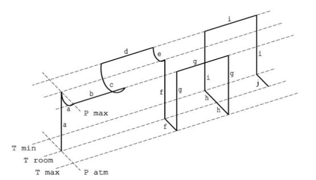
Figure F.1—Test Procedure for Pressure Temperature Cycle
F.24.2 Test Pressure and Temperature
The test pressure and temperature extremes shall be as specified in a validation procedure.
F.24.3 Test Procedure
Pressure shall be monitored and controlled during temperature change. The following procedure shall be performed.
NOTE The item letters of the steps of the procedure correspond to the letters shown in Figure F.1.
Apply the test pressure to the body shell at ambient temperature and maintain at 50% to 100% of test pressure
while raising temperature to the maximum.
b) Hold for a period of 1 hour minimum at test pressure.
c) Reduce the temperature to the minimum while maintaining 50% to 100% of test pressure.
d) Hold for a minimum period of 1 hour at test pressure.
e) Raise the temperature to ambient temperature while maintaining 50% to 100% of test pressure.
f) Release the pressure, and then raise the temperature to the maximum.
g) Apply the test pressure to the body shell, hold for a minimum period of 1 hour, and then release the pressure.
h) Reduce the temperature to the minimum.
i) Apply the test pressure to the body shell, hold for a minimum period of 1 hour, and then release the pressure.
j) Raise the temperature to ambient temperature.
F.25 Gas Body Test at Ambient Temperature
F.25.1 General
Gas shell testing at ambient temperature shall be conducted using the methodology indicated into I.7.1.
F.25.2 Leak Detection
Gas testing at ambient temperature shall be conducted with a method for leak detection.
NOTE 1 The product may be completely submerged in a liquid, or the product may be flooded in the seal areas being validated, such that all possible leak paths are covered.
NOTE 2 The product may be assembled with one end of a tube connected to a blind connector enclosing all possible leak paths being validated.
When one end of the tube is connected to a blind connector, the other end of the tube shall be immersed in a liquid or attached to a leakage measurement device.
NOTE 3 Other methods that can detect leakage accurately are acceptable.
F.25.2 Acceptance Criteria
The gas test at a temperature between 40 °F and 120 °F (4 °C and 50 °C) shall be acceptable if no sustained bubbles are observed. If leakage is observed, the rate shall be less than the rates shown in Table F.5, measured at atmospheric pressure, during specified pressure-hold periods.
Table F.5—Ambient Temperature Gas Leakage Acceptance Criteria for All Valve Types
| Seal Type | Allowable Leakage |
| Stem Seal | 5.5 cm3/h/NPS |
| Static (Bonnet Seal, End Connectors) | 1.5 cm3/h/NPS |
F.26 High Pressure Gas Seat Test at Ambient Temperature
Valves shall undergo a seat test that conforms to I.7.2
Leakage for soft-seated valves shall not exceed ISO 5208, Rate B
Leakage for lubricated plug valves shall not exceed ISO 5208, Rate A
For metal-seated valves, the leakage rate shall not exceed ISO 5208, Rate D.
For metal-seated check valves, the leakage rate shall not exceed ISO 5208, Rate F.
Actual leakage shall be recorded for all seat tests.
F.27 Low Pressure Gas Seat Test at Ambient Temperature
Valves shall undergo a seat test that conforms to I.6
Leakage for soft-seated shall not exceed ISO 5208, Rate B.
Leakage for lubricated plug valves shall not exceed ISO 5208, Rate A.
For metal-seated valves, the leakage rate shall not exceed ISO 5208, Rate D
For metal-seated check valves, the leakage rate shall not exceed ISO 5208, Rate F.
Actual leakage shall be recorded for all seat tests.
F.28 Final Force or Torque Measurement
The breakaway and running torques or forces shall be measured. For check valves provided with an external operator, torques or forces shall be measured without differential pressure on the closure member.
The procedure for final force or torque measurement shall be determined and documented by the manufacturer.
The operating forces or torques shall be within the manufacturer's specifications.