API 6D Annex B
API 6D Annex B shows examples of possible configurations for gate, plug, ball, check, and axial valves with flanged and welding ends for illustration purposes only. Other configurations not shown in this annex of the same type of valve may apply.
Annex B
(informative)
Examples of Valve Configurations
API 6D Annex B shows examples of possible configurations for gate, plug, ball, check, and axial valves with flanged and welding ends for illustration purposes only. Other configurations not shown in this annex of the same type of valve may apply.
Figure B.1—Axial Valve
Figure B.2— Ball Valve (Floating)
Figure B.3— Ball Valve (Side-entry Trunnion Mounted)
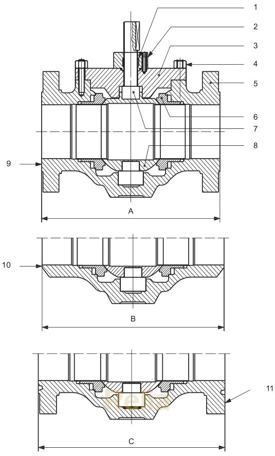
Figure B.4— Ball Valve (Top-entry Trunnion Mounted)
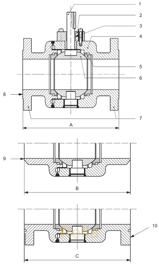
Figure B.5—Ball Valve (Welded-body Trunnion Mounted)
Figure B.6—Check Valve (Axial Flow)
Figure B.7—Check Valve (Full-opening Swing)
Figure B.8—Check Valve (Long Pattern, Single-plate Wafer-type)
Figure B.9—Check Valve (Long Pattern, Typical Dual-plate Wafer-type)
Figure B.10—Check Valve (Piston)
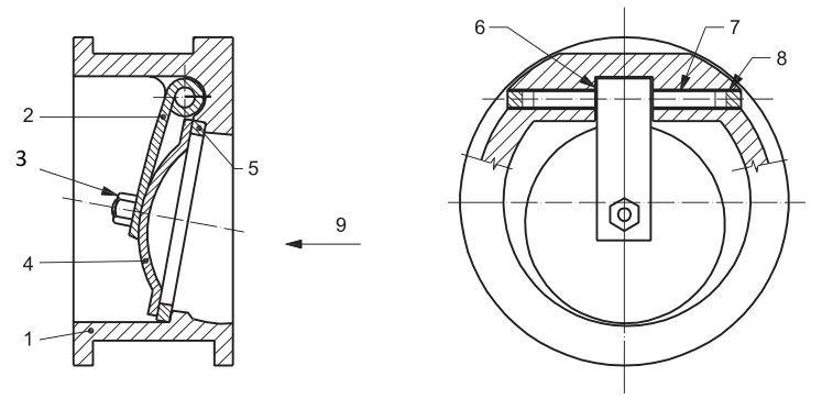
Figure B.11—Check Valve (Reduced-opening Swing)
Figure B.12—Check Valve, Short Pattern (Single-plate Wafer-type)
Figure B.13—Gate Valve (Expanding-gate/Rising-stem)
Figure B.14—Gate Valve (Slab-gate/Through-conduit Rising-stem)
Figure B.15— Plug Valve
Key Part
| Part No. | Part Name |
| 1 | stem |
| 2 | body |
| 3 | piston |
| 4 | piston rod guide |
| 5 | piston rod |
| 6 | piston nut |
| 7 | seat ring |
| 8 | end connector |
| 9 | raised face |
| 10 | welding end |
| 11 | ring joint groove |
A raised-face face-to-face dimension
B welding-end end-to-end dimension
C ring joint end-to-end dimension See Applicable Table in Annex C for dimensions A, B, and C.
B.1—Axial Valve
Key Part
| Part No. | Part Name |
| 1 | stem |
| 2 | stem seal |
| 3 | end connector |
| 4 | seat ring |
| 5 | ball |
| 6 | body bolting |
| 7 | body |
| 8 | raised face |
| 9 | welding end |
| 10 | ring joint groove |
A raised-face face-to-face dimension
B welding-end end-to-end dimension
C ring joint end-to-end dimension
NOTE See Applicable Table in Annex C for dimensions A, B, and C.
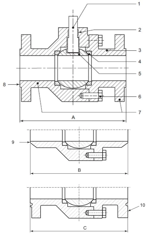
Figure B.2— Ball Valve (Floating)
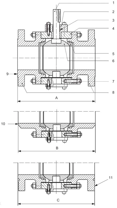
Key Part
| Part No. | Part Name |
| 1 | stem |
| 2 | body cover |
| 3 | stem seal |
| 4 | body |
| 5 | seat ring |
| 6 | ball |
| 7 | body bolting |
| 8 | end connector |
| 9 | raised face |
| 10 | welding end |
| 11 | ring joint groove |
A raised-face face-to-face dimension
B welding-end end-to-end dimension
C ring joint end-to-end dimension
NOTE See Applicable Table in Annex C for dimensions A, B, and C.
Figure B.3— Ball Valve (Side-entry Trunnion Mounted)
Key Part
| Part No. | Part Name |
| 1 | stem seal |
| 2 | bonnet cover |
| 3 | bonnet |
| 4 | body bolting |
| 5 | body |
| 6 | seat ring |
| 7 | stem |
| 8 | ball |
| 9 | raised face |
| 10 | welding end |
| 11 | ring joint groove |
A raised-face face-to-face dimension
B welding-end end-to-end dimension
C ring joint end-to-end dimension
NOTE See Applicable Table in Annex C for dimensions A, B, and C.
Figure B.4—Ball Valve (Top-entry Trunnion Mounted)
Key Part
| Part No. | Part Name |
| 1 | stem |
| 2 | bonnet cover |
| 3 | stem seal |
| 4 | body bolting |
| 5 | body |
| 6 | seat ring |
| 7 | end connector |
| 8 | raised face |
| 9 | welding end |
| 10 | ring joint groove |
A raised-face face-to-face dimension
B welding-end end-to-end dimension
C ring joint end-to-end dimension
NOTE See Applicable Table in Annex C for dimensions A, B, and C.
Figure B.5—Ball Valve (Welded-body Trunnion Mounted)
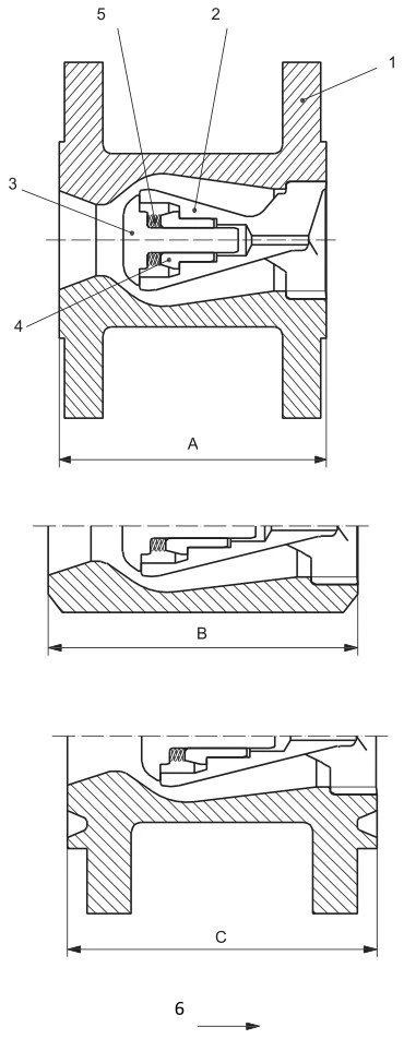
Key Part
| Part No. | Part Name |
| 1 | body |
| 2 | rod guidance |
| 3 | disc |
| 4 | bearing |
| 5 | spring |
| 6 | flow direction |
A raised-face face-to-face dimension
B welding-end end-to-end dimension
C ring joint end-to-end dimension
NOTE See Applicable Table in Annex C for dimensions A, B, and C.
Figure B.6—Check Valve (Axial Flow)
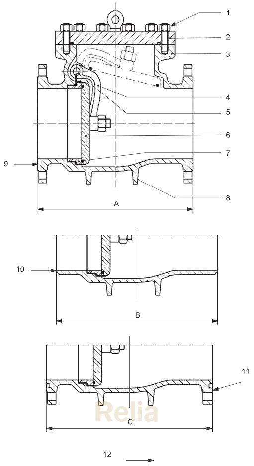
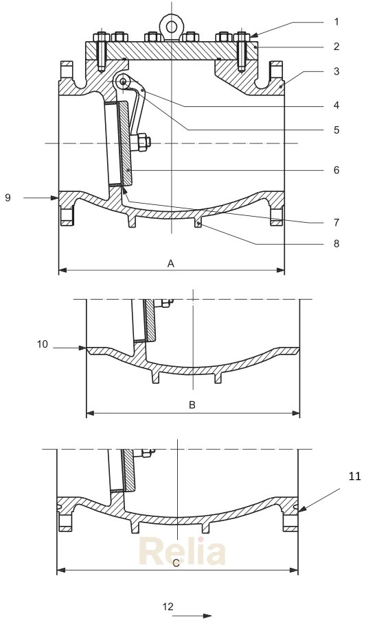
Key Part
| Part No. | Part Name |
| 1 | cover bolting |
| 2 | cover |
| 3 | body |
| 4 | clapper disc arm |
| 5 | shaft |
| 6 | clapper disc |
| 7 | seat ring |
| 8 | support legs |
| 9 | raised face |
| 10 | welding end |
| 11 | ring joint groove |
| 12 | direction of flow |
A raised-face face-to-face dimension
B welding-end end-to-end dimension
C ring joint end-to-end dimension
NOTE See Applicable Table in Annex C for dimensions A, B, and C.
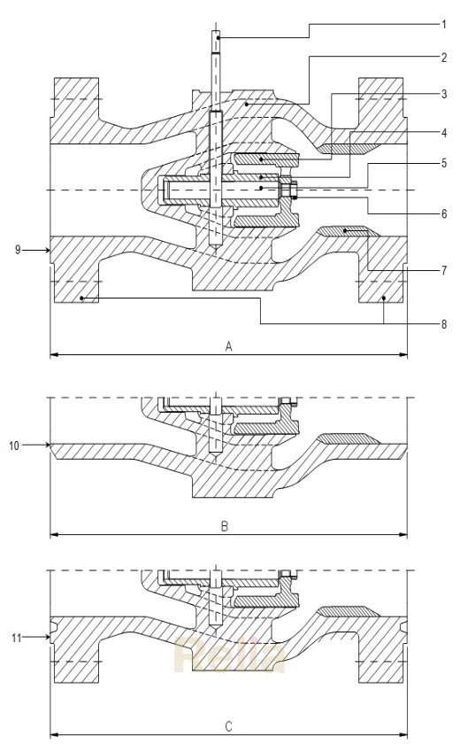
Figure B.7—Check Valve (Full-opening Swing)
Key Part
| Part No. | Part Name |
| 1 | body |
| 2 | hinge |
| 3 | nut |
| 4 | closure plate/stud assembly |
| 5 | seat ring |
| 6 | bearing spacers |
| 7 | hinge pin |
| 8 | hinge pin retainers |
| 9 | direction of flow |
Figure B.8—Check Valve (Long Pattern, Single-plate Wafer-type)
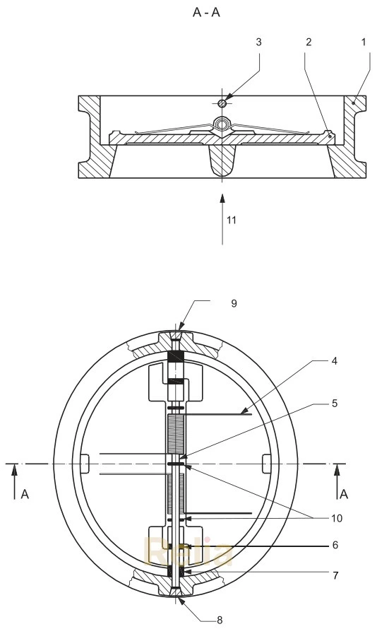
Key Part
| Part No. | Part Name |
| 1 | body |
| 2 | Closure plate |
| 3 | stop pin |
| 4 | spring |
| 5 | hinge pin |
| 6 | plate lug bearings |
| 7 | body lug bearings |
| 8 | stop pin retainers |
| 9 | hinge pin retainers |
| 10 | spring bearings |
| 11 | direction of flow |
Figure B.9—Check Valve (Long Pattern, Typical Dual-plate Wafer-type)
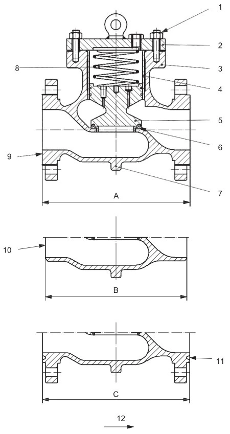
Key Part
| Part No. | Part Name |
| 1 | cover bolting |
| 2 | cover |
| 3 | body |
| 4 | piston |
| 5 | liner |
| 6 | seat ring |
| 7 | support legs |
| 8 | raised face |
| 9 | welding end |
| 10 | ring joint groove |
| 11 | direction of flow |
| 12 | cover bolting |
A raised-face face-to-face dimension
B welding-end end-to-end dimension
C ring joint end-to-end dimension
NOTE See Applicable Table in Annex C for dimensions A, B, and C.
Figure B.10—Check Valve (Piston)
Key Part
| Part No. | Part Name |
| 1 | cover bolting |
| 2 | cover |
| 3 | body |
| 4 | clapper disc arm |
| 5 | shaft |
| 6 | clapper disc |
| 7 | seat ring |
| 8 | support legs |
| 9 | raised face |
| 10 | welding end |
| 11 | ring joint groove |
| 12 | direction of flow |
A raised-face face-to-face dimension
B welding-end end-to-end dimension
C ring joint end-to-end dimension
NOTE See Applicable Table in Annex C for dimensions A, B, and C.
Figure B.11—Swing Check Valve (Reduced-opening)
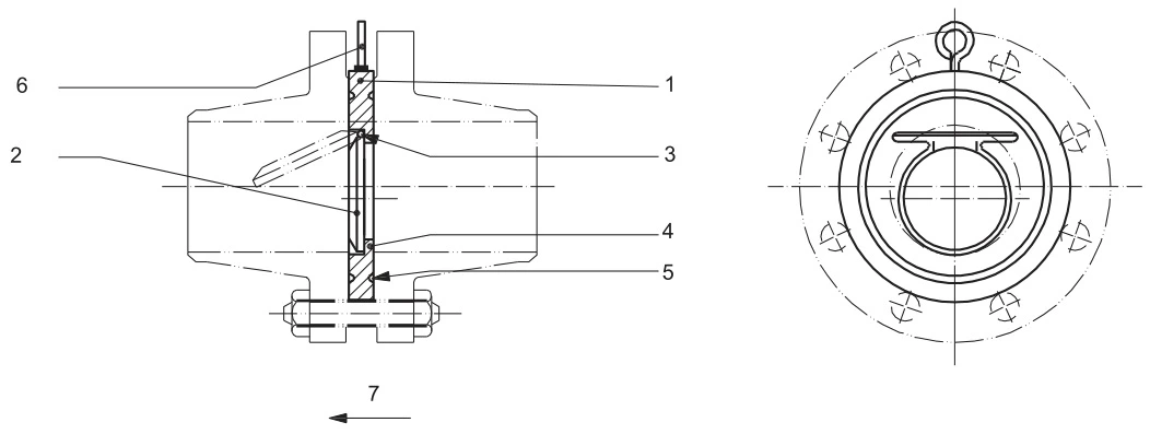
Key Part
| Part No. | Part Name |
| 1 | body |
| 2 | clapper |
| 3 | pin |
| 4 | clapper seal |
| 5 | body seal |
| 6 | lifting eye |
| 7 | direction offlow |
Figure B.12—Check Valve (Short Pattern, Single-plate Wafer-type)
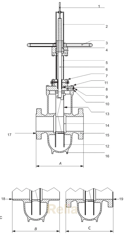
Key Part
| Part No. | Part Name |
| 1 | stem indicator |
| 2 | stem enclosure |
| 3 | handwheel |
| 4 | yoke nut |
| 5 | yoke |
| 6 | stem |
| 7 | yoke bolting |
| 8 | stem packing |
| 9 | relief valve |
| 10 | bonnet |
| 11 | bonnet bolting |
| 12 | gate guide |
| 13 | gate assembly |
| 14 | seat ring |
| 15 | body |
| 16 | support ribs or |
| 17 | raised face |
| 18 | welding end |
| 19 | ring joint groove |
A raised-face face-to-face dimension
B welding-end end-to-end dimension
C ring joint end-to-end dimension
NOTE See Applicable Table in Annex C for dimensions A, B, and C.
Figure B.13—Gate Valve (Expanding-gateRising-stem)
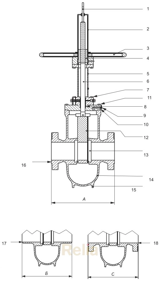
Key Part
| Part No. | Part Name |
| 1 | stem indicator |
| 2 | stem enclosure |
| 3 | handwheel |
| 4 | yokenut |
| 5 | yoke |
| 6 | stem |
| 7 | yoke bolting |
| 8 | stem packing |
| 9 | reliefvalve |
| 10 | bonnet |
| 11 | bonnet bolting |
| 12 | gate |
| 13 | Seat ring |
| 14 | body |
| 15 | support ribs or legs |
| 16 | raised face |
| 17 | welding end |
| 18 | ring joint groove |
A raised-face face-to-face dimension
B welding-end end-to-end dimension
C ring joint end-to-end dimension
NOTE See Applicable Table in Annex C for dimensions A, B, and C.
Figure B.14—Gate Valve (Slab-gate/Through-conduit Rising-stem)
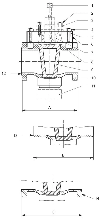
Key Part
| Part No. | Part Name |
| 1 | lubricator screw |
| 2 | gland studs and nuts |
| 3 | gland |
| 4 | cover studs and nuts |
| 5 | cover |
| 6 | cover gasket |
| 7 | stem packing |
| 8 | lubricant check valve |
| 9 | plug |
| 10 | body |
| 11 | stop collar |
| 12 | raised face |
| 13 | welding end |
| 14 | ring joint groove |
A raised-face face-to-face dimension
B welding-end end-to-end dimension
C ring joint end-to-end dimension
NOTE See Applicable Table in Annex C for dimensions A, B, and C.
Figure B.15—Plug Valve