API 622 Fugitive Emissions Test
Type Testing of Process Valve Packing for Fugitive Emissions
1 Scope
API 602 standard specifies the requirements for comparative testing of valve stem packing for process applications where fugitive emissions are a consideration. Packing(s)shall be suitable for use at service temperatures -29 ° ℃ to 538 ° ℃(-20 °F to 1000°F). Factors affecting fugitive emissions performance that are considered by this standard include temperature, pressure, thermal cycling, mechanical cycling, and corrosion.
API 602 standard is not intended to replace type testing of valve assemblies or valve production testing.
This standard establishes requirements and parameters for the following tests:
a) fugitive emissions,
b) corrosion, and
c) packing material composition and properties.
Test methods apply to packing for use in on-off valves with the following stem motion(s):
a) rising stem, and
b) rotating stem.
The test for fugitive emissions is based upon elements of EPA Method 21, providing comparative values of packing performance.
4 Fugitive Emissions Test
4. 1 Test Fixture
4. 1. 1 The test stand packing gland is constructed as a fixture designed to simulate a typical valve. A test gland arrangement with a combined leak detection and gland flange is shown in Figure 1. The test fixtureshall orient the stem in a horizontal position and shall be constructed so as not to affect test results. The use of bushings is allowed as necessary. Test stands may be equipped with multiple test fixtures. See Annex B for construction details.
4.1.1.1 Test fixture packing gland dimensions and tolerances shall be as follows.
a) Stem diameter:25. 4 mm+0. 0 mm or-0. 2 mm(1. 000 in. +0. 0 in. or-0. 008 in. ).
b) Stem straightness:Max. 0. 04 mm per 305 mm (0. 0016 in. per 12 in. ).
c) Stem cylindricity:0. 04 mm(0. 0016 in. )Max.
d) Stem surface finish:0. 40 μm Ra to 0. 80 μm Ra(16 μ-in. Ra to 32 μ-in. Ra).
e) Stuffing box diameter:38. 1 mm+0. 25 mm or-0. 0 mm(1. 5 in. +0. 010 in. or-0. 0 in. ).
f) Stuffing box depth:44. 5 mm±1. 5748 mm(1. 75 in. ±0. 062 in. ).
g) Stuffing box surface finish:3. 20 μm Ra+1. 25 μm Ra or-0. 625μm(125 μ-in. Ra+50 μ-in. Ra or-25 μ-in. )
4. 1 Test Fixture
4. 1. 1 The test stand packing gland is constructed as a fixture designed to simulate a typical valve. A test gland arrangement with a combined leak detection and gland flange is shown in Figure 1. The test fixtureshall orient the stem in a horizontal position and shall be constructed so as not to affect test results. The use of bushings is allowed as necessary. Test stands may be equipped with multiple test fixtures. See Annex B for construction details.
h) Gland bottom machined flat parallel to gasket surface:Max. 0. 15 mm (0. 006 in. ).
i) Gland to stuffing box diametrical clearance:0. 13 mm to 0. 38 mm (0. 005 in. to 0. 015 in. ). j)Stem to gland (flange) diametrical clearance:0. 5 mm to 0. 8 mm(0. 020 in. to 0. 030 in. ).
k) Gland stud diameter:5/g in. -11 UNC (2 pieces, length per Figure 1).
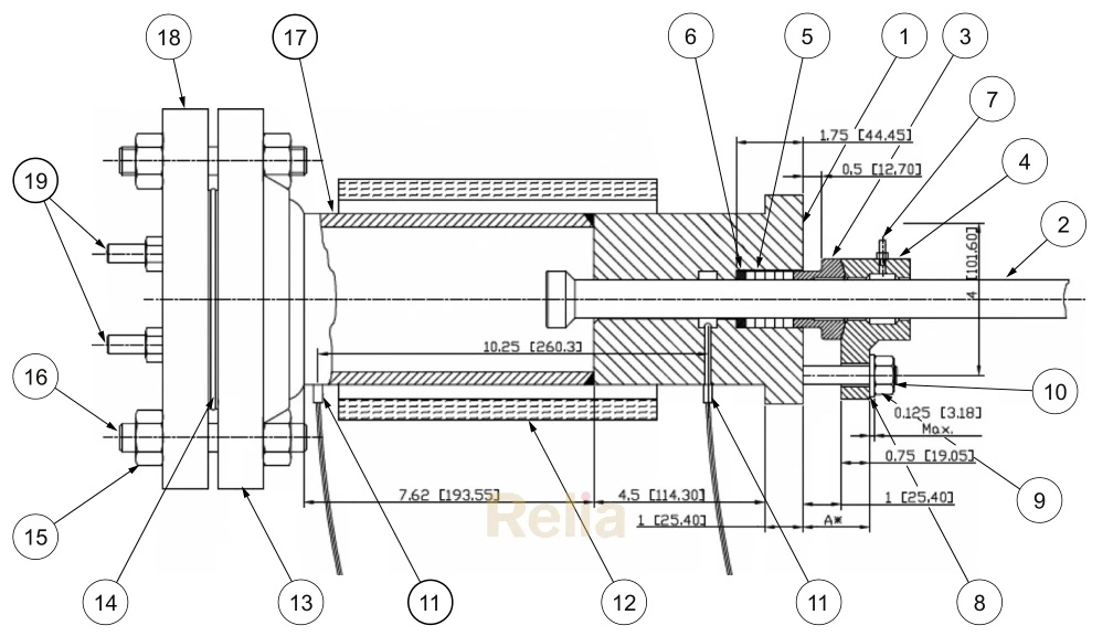
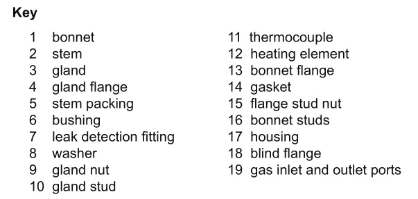
Figure 1—Emission Test Fixture
4. 1. 1. 2 Test fixture components shall be constructed of carbon steel materials except for the following.
a) Stem:ASTM A182 Grade F6a Rc15-28. 8 (200-275 HB).
b) Gland bolts and studs:ASTM A193 Grade B7.
c) Gland nuts:ASTM A194 Grade 2H.
d) Housing:DN 100 (4 in. )Schedule 80 Seamless Pipe or A-105.
e) Flanges:DN 100(4 in. )Class 300 Per ASME B16. 5(material group ASME B16. 5 Table F2-1. 1)or ASTM A105.
4. 1. 2 Mechanical Cycle
The test fixtureshall be equipped with an actuator capable of stroking the test stem to simulate the mechanical cycle of a valve as follows.
a)Rising stem:
Rate:3 mm to 5 mm(0. 12 in. to 0. 20 in. )per second.
Stroke:102 mm±3mm (4 in. ±0. 12 in. ).
b)Rotating stem:
Rate:10°to 15°per second.
Rotation:90⁰±5° .
4. 1. 3 External Loads
The actuator(s)shall not apply any transverse forces, such as side load, to the test stem.
4. 1. 4 Temperature Monitoring:
The test fixture(s)shall be equipped with thermocouples for continuously monitoring temperature during thermal cycling.
4. 1. 5 Temperatureshall be monitored and recorded at the following two locations:
a)the flow line of the test chamber, and
b)adjacent to the stuffing box.
4. 1. 6 The thermocouple adjacent to the stufing box shall control the test temperature.
4. 1. 7 The temperature at the flow line thermocoupleshall be the reference measurement.
4. 1. 8 The fixtureshall be heated using an external heat source, blanket, heating coils or other suitable equipment. NOTE Refer to ASME Section VIll Division 2, Section 5. 5, for information on fatigue analysis methodology.
4. 2 Leak Test Equipment Selection and Calibration
4. 2. 1 Monitoring equipment shall be a flame ionization organic vapor analyzer capable of providing on-board data logging with digital readout. The equipment shall be certified as intrinsically safe for use with the test fluid.
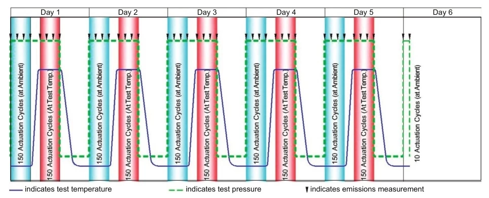 Figure 2—Mechanical and Thermal Cycling Diagram
4. 2. 2 The equipment shall meet the following performance requirements in the flame ionization mode using methane as the test fluid.
a) Variation:less than±2 % at 100 ppm.
b) Dynamic range:1. 0 ppm to 50, 000 ppm.
c) Linear range:1. 0 ppm to 10, 000 ppm.
d) Minimum detectable level (defined as 2 times the peak noise):300 ppb hexane.
e) Maximum response time to reach final value:3 seconds.
f) Maximum recovery time to return to 10 %of initial value:5 seconds.
g) Sample flow rate at probe inlet:1. 14 l/min to 1. 51 I/min (0. 30 gal/min to 0. 40 gal/min).
4. 2. 3 The testing equipment shall be calibrated according to the manufacturer's directions. A current record of test equipment calibrationshall be maintained by the test facility.
4. 2. 4 The test equipment shall be inspected prior to each use to insure against fouling of the detector probe. This shall be done to EPA Method 21, using an external calibration gas with a known methane concentration.
4. 3 Packing Selection and Installation
4. 3. 1 Pre-qualification
Packing submitted for type testing shall be certified by the packing manufacturer to be suitable for the conditions indicated in Section 1 of this standard.
4. 3. 2 Packing Selection
4. 3. 2. 1 Test packing shall be selected at random from either:
a)a standard production lot as supplied by the manufacturer, or b)a distributor stock.
4. 3. 2. 2 Test packing shall be 6. 3 mm(1/4 in. )cross-section for the test fixture. Validation of a random selection process shall be provided to the testing facility. Packing in productionshall be pulled from standard production line. Random selection is not applicable for prototype material.
4. 3. 3 Packing Installation
A qualified laboratory representative or technicianshall install the packing according to the manufacturer's standard installation instructions except that the maximum packing bolt stress shall not exceed 172, 369 kPa (25, 000 psi). However, the packing stress(load)during the testing shall not exceed the packing manufacturer's recommended maximum value.
4. 3. 3. 1 Instructions for all packing installations:
a) all test fixture components shall be thoroughly cleaned with acetone or equivalent solvent prior to testing;
b) any reconditioned parts shall be inspected and shall comply with the requirements of 4. 1. 2;
c) components shall be inspected for damage prior to assembly;
d) caution shall betaken to avoid contact between the stem and gland;
e) fasteners shall be lubricated;
f) gland (flange)height measured from a specific datum shall be recorded;
g) special preparation of the packing or assembly components is prohibited.
4. 4 Test Procedure
4. 4. 1 Test Fluid
The test fluid used shall be dry methane gas, 97 %minimum purity, subjected to a temperature range from ambient to 260℃(500°F)and pressures from 0 kPag to 4, 137 kPag (0 psig to 600 psig)(see Figure 2).
4. 4. 2 Mechanical and Thermal Cycling
4. 4. 2. 1 Packing in test rigs shall be subject to a total of 1510 mechanical cycles and 5 thermal cycles per Figure 2. Mechanical and thermal cycling shall begin with the test fixture at ambient temperature.
4. 4. 2. 2 Test Profile
The following are recommendations for accomplishing the testing cycles in Figure 2.
a)Test duration of five, 8 hour maximum days, and one, 2 hour maximum mechanical cycling day.
b)Mechanical cycles per day are 300.
c)Temperature cycle per day is 1.
一 Pressure stays at 4, 137 kPag±34 kPa(600 psig±5 psig).
一 Cycles at ambient are 150.
一 Cycles at 260 ° ℃±3℃(500°F±5°F)are 150.
d)Reduce the pressure to zero at the end of each day (thermal cycle).
e)Minimum daily cycling is to be divided up as follows:
一 Ambient cycling at pressure is 3 hours.
一 Max. 2 hours to bring up to temperature (no cycling during this time).
一 Elevated temperature cycling is 3 hours.
一 Daytime or Overnight cool down with no cycling during this period.
4. 4. 3 Leak Measurement
4. 4. 3. 1 Leak measurements shall be conducted initially at the start of each day and at the completion of every 50 cycles. For each measurement, a minimum of 10 readings shall be taken over a one minute duration. The average readingshall be calculated and recorded. If any reading is more than fifty percent greater than the average, except for when the average leakage rates are less than 10 ppmv, the readings shall be repeated.
4. 4. 3. 2 The leak measurement shall be conducted using fixed detection probes located at the 12 AM and 12 PM positions directly above the potential leak points as shown in Figure 4.
4. 4. 3. 3 Leak measurements shall betaken while the stem is in the static condition.
4. 4. 3. 4 The connections to the fixture and methane leak detectorshall be made using tubing having the same inside diameter as the standard leak probe and connected as shown in Figure 3 and Figure 4.
4. 4. 3. 5 The leak detector shall measure the combined flows from the stem outside diameter (OD)and from the gland OD
4. 4. 3. 6 The emissions leak test system shall conform to all local and governmental safety standards and shall be equipped with pressure relief valve(s)and rupture disc and vents.
4. 4. 4 Packing Adjustment
4. 4. 4. 1 At the option of the packing manufacturer, one adjustment to the manufacturer's specified gland load may be made if the leak rate performance, as defined in paragraph 4. 4. 3. 1, exceeds the manufacturer's maximum allowable leakage.
4. 4. 4. 2 Mechanical cycling shall be discontinued during a necessary adjustment.
4. 4. 4. 3 Adjustments shall be reported as packing gland bolt torque values and as measured by recording the change in clearance between the gland flange and the top of the bonnet (reference dimension A*per Figure 1 and Figure 4)or by a fixed height gauge. The gauge shall provide readout in 0. 025 mm (0. 001 in. )increments.
4. 4. 4. 4 Flats of adjustmentshall be indicated by use of a line marked on the gland flange and gland nuts at the start of the test.
4. 4. 4. 5 The test should end if leakage exceeds 500 ppm after the one permitted adjustment.
4. 4. 5 Recording and Documentation
Fugitive emissions test results shall be provided on the Fugitive Emissions Test Report Summary provided in Annex A. 1.
4. 4. 5. 1 Leak measurements shall be recorded at the beginning of the test and at established intervals throughout the test, as required per Figure 2.
4. 4. 5. 2 The packing adjustmentshall be recorded and the cycle number noted along with the gland bolt torque prior to the adjustment. The gland bolt torque is for information only.