API 608-Metal Ball Valves—Flanged, Threaded, and Welding Ends
API 608 standard specifies the requirements for metal ball valves suitable for petroleum, petrochemical, and industrial applications.
1 Scope
1.1 This standard specifies the requirements for metal ball valves suitable for petroleum, petrochemical, and industrial applications that have:
— flanged ends in sizes DN 15 through DN 600 (NPS 1/2 through NPS 24);
— butt-welding ends in sizes DN 15 through DN 600 (NPS 1/2 through NPS 24);
— socket-welding ends in sizes DN 8 through DN 50 (NPS 1/4 through NPS 2);
— threaded ends in sizes DN 8 through DN 50 (NPS 1/4 through NPS 2).
Corresponding to the nominal pipe sizes in ASME B36.10M.
1.2 This standard applies to metal ball valves with pressure classes as follows:
一 flanged ends in Classes 150, 300, and 600;
一 butt-welding ends in Classes 150, 300, and 600;
一 socket-welding ends in Classes 150, 300, 600, and 800;
一 threaded ends in Classes 150, 300, 600, and 800.
1.3 This standard establishes requirements for bore sizes described as:
一 full bore;
一 single reduced bore;
一 double reduced bore.
1.4 This standard applies to floating (seat-supported) ball (Figure B.1) and trunnion ball valve designs (Figure B.2). These figures are to be used only for the purpose of establishing standard nomenclature for valve components一 other floating and trunnion designs also exist.
1.5 This standard establishes additional requirements for ball valves that are otherwise in full conformance to the requirements of ASME B16.34, Standard Class.
4 Pressure-Temperature Ratings
4.1 Valve Rating
The valve pressure-temperature rating shall be the lesser of the shell rating or the seat rating.
4.2 Shell Rating
The valve shell pressure-temperature rating shall be the rating for the shell material as listed for Standard Class in ASME B16.34 (see 6.1 for definition of shell and description of shell materials).
4.3 Seat and Seal Rating
4.3.1 Seat Ratings for PTFE and R-PTFE
Valves employing polytetrafluoroethylene (PTFE) or modified PTFE seats and valves employing reinforced polytetrafluoroethylene (R-PTFE) or modified R-PTFE seats shall have pressure-temperature ratings equal or higher than the values shown in Table 1 and Table 2.
4.3.2 Seat Ratings— Other Materials
Seat pressure-temperature ratings for seat materials other than PTFE or R-PTFE shall be the manufacturer's standard. Seats made from hard materials such as solid cobalt chrome alloy, ceramics, or metal seats coated with hard materials such as carbide coatings are also acceptable and shall have seat pressure-temperature ratings per the manufacturer^ standard. The published seat pressure-temperature ratings shall not exceed the manufacturer^ published shell ratings.
Table 1—Minimum Seat Pressure-Temperature Rating—bar
| Temperature ℃ | Temperature °F | PTFE a and Modified PTFE Seats |
Trunnion | R-PTFE a and Modified R-PTFE Seats |
Trunnion | ||||
| Floating Ball Design | Floating Ball Design | ||||||||
| DN<50 | 50< DN<100 | DN>100 | DN>50 | DN<50 | 50<DN<100 | DN>100 | DN>50 | ||
| -29 to 38 | -20 to 100b | 69.0 | 51.0 | 19.7 | 51.0 | 75.9 | 51.0 | 19.7 | 51.0 |
| 66 | 150 | 56.9 | 42.1 | 16.2 | 42.1 | 63.8 | 43.1 | 16.6 | 43.1 |
| 93 | 200 | 45.5 | 33.4 | 13.1 | 33.4 | 52.4 | 35.5 | 13.8 | 35.5 |
| 122 | 250 | 34.5 | 24.5 | 9.7 | 24.5 | 39.7 | 27.6 | 10.7 | 27.6 |
| 149 | 300 | 22.4 | 15.9 | 6.2 | 15.9 | 29.0 | 19.0 | 7.6 | 19.0 |
| 177 | 350 | 11.7 | 6.9 | 2.8 | 6.9 | 17.2 | 8.6 | 3.5 | 8.6 |
| 205 | 400 | — | — | — | — | 5.5 | 3.4 | 1.4 | 3.4 |
NOTE For any given pressure class, the seat pressure-temperature rating shall not exceed the shell ratings in ASME B16.34.
a Polytetrafluoroethylene.
b Consult manufacturer for minimum design temperature rating of seats.
Table 2—Minimum Seat Pressure-Temperature Rating-psig
| Temperature ℃ | Temperature °F | PTFE a and Modified PTFE Seats | Trunnion | R-PTFE a and Modified R-PTFE Seats |
Trunnion | ||||
| Floating Ball Design | Floating Ball Design | ||||||||
| NPS<2 | 2 < NPS < 4 | NPS >4 | NPS >2 | NPS <2 | 2 < NPS < 4 | NPS >4 | NPS >2 | ||
| -29 to 38 | -20 to 100 b | 1000 | 740 | 285 | 740 | 1100 | 740 | 285 | 740 |
| 66 | 150 | 825 | 610 | 235 | 610 | 925 | 625 | 240 | 625 |
| 93 | 200 | 660 | 485 | 190 | 485 | 760 | 515 | 200 | 515 |
| 122 | 250 | 500 | 355 | 140 | 355 | 575 | 400 | 155 | 400 |
| 149 | 300 | 325 | 230 | 90 | 230 | 420 | 275 | 110 | 275 |
| 177 | 350 | 170 | 100 | 40 | 100 | 250 | 125 | 50 | 125 |
| 205 | 400 | — | — | — | — | 80 | 50 | 20 | 50 |
NOTE For any given pressure class, the seat pressure-temperature rating shall not exceed the shell ratings in ASME B16.34.
a Polytetrafluoroethylene.
b Consult manufacturer for minimum design temperature rating of seats.
5 Design
5.1 General
Valves designed and manufactured in accordance with this standard shall meet the requirements of Standard Class valves per ASME B16.34 and additional requirements as specified in this standard.
5.2 Flow Passageway
The flow passageway is the circular opening in the ball and extends outward to both valve end connections, which can be flanged, threaded, socket-welding, or butt-welding types. The bore of this flow passageway is categorized in this standard as full bore, single reduced bore, and double reduced bore. Full bore, single reduced bore, and double reduced bore valves shall have a flow passageway such that a cylinder with the diameters shown in Table 3 can be passed through when the handle or gear operator is moved to the full open position stop.
Table 3—Cylinder Diameter for Categorizing Bore Size
| DN | Full Bore | Single Reduced Bore | Double Reduced Bore | NPS | |||
| mm | in. | mm | in. | mm | in. | ||
| 8 | 5 | 0.20 | n/a | n/a | n/a | n/a | 1/4 |
| 10 | 8 | 0.32 | 5 | 0.20 | n/a | n/a | 3/8 |
| 15 | 11 | 0.44 | 8 | 0.31 | n/a | n/a | 1/2 |
| 20 | 17 | 0.68 | 12 | 0.47 | 8 | 0.31 | 3/4 |
| 25 | 24 | 0.94 | 17 | 0.68 | 14 | 0.56 | 1 |
| 32 | 30 | 1.19 | 22 | 0.87 | 18 | 0.71 | 1 1/4 |
| 40 | 37 | 1.44 | 27 | 1.06 | 23 | 0.91 | 1 1/2 |
| 50 | 49 | 1.94 | 37 | 1.44 | 30 | 1.19 | 2 |
| 65 | 62 | 2.44 | 49 | 1.94 | 37 | 1.44 | 2 1/2 |
Table 3—Cylinder Diameter for Categorizing Bore Size (Continued)
| DN | Full Bore | Single Reduced Bore | Double Reduced Bore | NPS | |||
| mm | in. | mm | in. | mm | in. | ||
| 80 | 75 | 2.94 | 56 | 2.19 | 49 | 1.94 | 3 |
| 100 | 100 | 3.94 | 75 | 2.94 | 62 | 2.44 | 4 |
| 150 | 151 | 5.94 | 100 | 3.94 | 75 | 2.94 | 6 |
| 200 | 202 | 7.94 | 151 | 5.94 | 100 | 3.94 | 8 |
| 250 | 251 | 9.88 | 202 a | 7.94 a | 151 | 5.94 | 10 |
| 300 | 302 | 11.88 | 251 b | 9.88 b | 202 | 7.94 | 12 |
| 350 | 334 | 13.14 | 302 | 11.88 | 251 | 9.88 | 14 |
| 400 | 385 | 15.15 | 334 | 13.14 | 302 | 11.88 | 16 |
| 450 | 436 | 17.16 | 385 | 15.15 | 334 | 13.14 | 18 |
| 500 | 487 | 19.17 | 436 | 17.16 | 385 | 15.15 | 20 |
| 600 | 586 | 23.07 | 487 | 19.17 | 436 | 17.16 | 24 |
a For one-piece (unibody) design the minimum flow passage is 186 mm (7.32 in.).
b For one-piece (unibody) design the minimum flow passage is 227 mm (8.94 in.).
5.3 Body
5.3.1 The wall thicknesses of the valve body (see note) shall be in accordance with the requirements of ASME B16.34 for the applicable Standard Class. ASME wall thicknesses are based on the Standard Class of valve and not the pressure-temperature ratings of 4.1.
NOTE Body may be comprised of multiple components, such as body, body cap, etc.
5.3.2 Face-to-face dimensions of flanged valves and end-to-end dimensions of butt-welding end valves shall conform to ASME B16.10 ball valves—long or short pattern.
5.3.3 End-to-end dimensions for threaded and socket-welding end valves shall be per the manufacturer^ standard.
5.3.4 The dimensions and facing finish of end flanges shall conform to ASME B16.5.
5.3.5 Butt-welding ends shall conform to the requirements of ASME B16.25 with an inside diameter (denoted as B in ASME B16.25) tolerance per ASME B16.34. DN 50 (NPS 2) and smaller butt-weld end valves shall conform to API 602.
5.3.6 Socket-welding ends shall conform to the requirements of ASME B16.11, except minimum wall thicknesses shall conform to Table 4 of ASME B16.34.
5.3.7 Threaded ends shall have taper pipe threads in accordance with ASME B1.20.1, and the minimum wall thicknesses shall conform to Table 4 of ASME B16.34.
5.3.8 End flanges and bonnet flanges shall be cast or forged integral with the body; except that cast or forged flanges attached by full penetration butt-welding may be used if agreed to by the purchaser. Valves having flanges attached by welding shall meet the requirements of Paragraph 2.1.6 of ASME B16.34.
5.3.9 Upstream sealing, trunnion-mounted ball valves shall have a test port into the body cavity between seats to allow seat testing as specified in API 598. This test port shall have taper pipe threads in accordance with ASME B.1.20.1 and shall be fitted with a solid test plug conforming to ASME B16.11. Additional tapped openings are permitted only when specified in the purchase order and shall have taper pipe threads in accordance with ASME B.1.20.1.
5.3.10 If drain, bypass, or other types of auxiliary connections are specified in the purchase order, they shall comply with the requirements of ASME B16.34.
5.3.11 When specified in the purchase order, body cavity overpressure shall be in accordance with ASME B16.34.
5.4 Antistatic Design (Electrical Continuity Between Ball-Stem-Body)
Valves shall incorporate an antistatic feature that insures electrical continuity between the stem and body of valves < DN 50 (< NPS 2) and between the ball, stem, and body of valves > DN 50 (> NPS 2). The antistatic feature shall have electrical continuity across the discharge path with a resistance not exceeding 10 ohms from a power source not exceeding 12 VDC when type tested on a new, dry, as-built valve after open-close position cycling of the valve at least five times.
5.5 Ball-Stem Design and Construction
5.5.1 The valve shall be designed to ensure that if a failure occurs at the stem-to-ball connection or of the stem itself within the pressure boundary, no portion of the stem is ejected by internal pressure.
5.5.2 The torsional strength of both the stem-to-ball connection and the portion of the stem within the pressure boundary (below top of packing) shall exceed the torsional strength of the stem portion above the pressure boundary (above the top of the packing) by at least 10 % at the maximum valve rated temperature.
5.5.3 The stem and the ball-to-stem connection shall be designed such that no permanent deformation occurs and no failure of any part occurs when a force applied to the lever or gear operator handwheel produces a torque equal to the greater of:
— 20 N-m (15ft-lb) or
一 twice the manufacturer^ maximum published torque.
The manufacturer^ maximum published torque shall be based upon clean, dry air service at the maximum differential pressure rating of the valve.
5.6 Ball Construction
Ball shall have a cylindrical bore and shall be of solid one-piece construction. Other constructions such as “hollow”- type, cored cavity, or sealed cavity may be furnished only if agreed to by the purchaser.
5.7 Packing Glands and Gland Bolting
5.7.1 Adjustable packing glands shall be accessible for resealing stem packing without the disassembly of valve parts or operator parts.
5.7.2 Packing glands that are threaded into bodies or covers or onto stems shall not be used for valve sizes greater than DN 80 (NPS 3) unless otherwise specified by purchaser. (See Figure B.1 and Figure B.2 for parts identification.)
5.7.3 Vertically split glands shall not be used.
5.7.4 When used, gland bolts shall pass through holes in the packing gland. The use of open slots is not permitted on any portion of the packing gland.
5.7.5 Packing gland bolts shall be designed so that the bolt stress shall not exceed 1/3 of the ultimate tensile strength of the bolting material when compressing packing material to a compressive stress of 38 MPa (5500 PSI) at 38 ℃(100 °F).
5.8 Operation
5.8.1 Unless otherwise specified on the purchase order, manually operated valves shall be equipped with lever-type handles.
5.8.2 Gear operators shall be fitted with handwheels and shall be sized to comply with the requirements of 5.8.3.
5.8.3 Unless otherwise specified by the purchaser, the length of the lever handle or the gear ratio, efficiency, and handwheel diameter of gear operators shall be designed so that the required input force to fully open and close the valve shall not exceed 360 N (80 lb) when operating the valve at the manufacturer^ maximum published torque as described in 5.5.3.
5.8.4 Valves shall be closed by rotating the closure device (lever or handwheel) in a clockwise direction.
5.8.5 Position stops shall be provided for both fully open and fully closed positions of the valve.
5.8.6 Handwheels on manual gear operators shall be marked to indicate the direction of opening and/or closing.
5.8.7 Lever-type handles shall be parallel to the ball bore so that the lever always indicates the ball bore position. If the purchaser specifies round or oval direct-mounted handwheels, a permanent means of indicating the ball bore position shall be included in the handwheel design.
5.8.8 An indication parallel with the position of ball bore of the valve shall be integral with the valve stem. This indication may be by permanent marking to the top of the stem, keyways, or by the shape of the exposed stem portion.
5.8.9 Levers, handwheels, and other operating mechanisms shall be fitted so that they may be removed and replaced without affecting the integrity of the stem seal(s), body seal(s), or stem retention means.
5.8.10 Lever or manual gear operators shall be designed so that the lever or gear operator cannot be assembled to the valve other than in the correct configuration to indicate open and closed positions.
5.8.11 When specified in the purchase order, valves shall be furnished with a lockable device that accepts a purchaser-supplied padlock that allows the valve to be locked in both the fully open and fully closed positions. The lockable device shall be designed such that a lock with a 8-mm (5/i6-in.) diameter shank, not more than 102 mm (4.0 in.) long, can be inserted directly through hole(s) in lockable device and locked. Provision for lockable device is permitted, even when not specified on purchase order.
5.8.12 Position stops integral with packing gland, gland flange, or gland bolting shall not be used.
5.9 End Flange Face Interruptions
5.9.1 Ring-shaped radial gaps in the faces of end flanges of flanged ball valves, located in the sealing surface of a centered ASME B16.20 spiral-wound gasket, shall not exceed 0.75 mm (0.030 in.); see dimension in Figure 1. An example of this condition is the radial gap that exists between the outer diameter of a body insert and the inner bore of the body end flange of a valve as shown in Figure B.1.
5.9.2 For ball valves designed with a body insert as shown in Figure B.1, with a gasket seating face outer diameter located within the sealing area of a centered ASME B16.20 spiral-wound gasket, the body insert flange face shall not protrude beyond the valve body end flange face. The body insert flange face shall not be recessed below the body end flange face by more than 0.25 mm (0.010 in.). See dimension a in Figure 1.
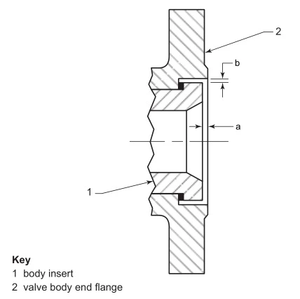
Figure 1—Flange Face Interruption Limits
5.10 Valve Shell Joints
5.10.1 Nut and bolt head bearing surfaces of shell parts assembled by bolting shall be perpendicular to the centerline of tapped or clearance holes for the fasteners within ± 1.0°.
5.10.2 Bolting used for assembly of shell joints shall be studs with nuts or cap screws. Nuts shall be semifinished hexagons conforming to ASME B18.2.2. Bolts and studs shall be threaded in conformance to ASME B1.1 unless purchaser specifies metric series bolting. Bolting 25 mm (1 in.) or smaller shall have coarse (UNC) threads; bolting larger than 25 mm (1 in.) shall be 8 thread series (8 UN). Bolt and stud threads shall be Class 2A, and nut threads shall be Class 2B per ASME B1.1.
5.10.3 Each bolted or threaded shell joint calculation shall be in accordance with the requirements of ASME B16.34, Section 6.4.
6 Materials
6.1 Shell
The shell, which comprises the body, body cover, body insert, body cap, and trunnion cap, shall be of materials specified in ASME B16.34. See Figure B.1 and Figure B.2.
6.2 Trim
The internal metal parts of the valve, including ball, stem, metal seats, and seat retainers shall be of the same nominal chemical composition as the shell and have mechanical and corrosion-resistance properties equivalent to or better than those of the shell. Purchaser may specify trim materials with greater corrosion resistance or higher strength than the shell. See Figure B.1 and Figure B.2.
6.3 Bolting
Unless an alternate bolting material is specified by the purchaser, body, cover, shell joint, and packing gland bolting shall be intermediate strength as specified in ASME B16.5 as a minimum. Purchaser may specify higher grades of bolting materials.
6.1 Stem Seals, Body Seals, and Gaskets
Materials for stem seals, body seals and gaskets shall be suitable for use at the maximum operating temperature and corresponding maximum pressure rating of the valve as stated by the valve manufacturer. Metallic parts of any gasket shall have corrosion resisting properties equal to or superior to shell material.
6.2 Identification Plate(s)
The material of identification plate(s) shall be austenitic stainless steel or nickel alloy. The identification plate(s) shall be attached to the valve body by welding or by pins made from same materials allowed for identification plate.
6.3 Threaded Plugs
Threaded plugs used for sealing tapped openings shall have the same nominal composition as the shell material. Plugs manufactured from any type of cast iron shall not be used.
6.4 When specified in the purchase order, shell, trim, and bolting materials shall comply with NACE MR 0103.
7 Inspection, Examination, and Testing
7.1 Inspection and Examination
7.1.1 The valve manufacturer shall examine each valve to ensure compliance to this standard.
7.1.2 If inspection by the purchaser is specified in the purchase order, inspection shall be in accordance with API 598. Examination by the manufacturer shall be as specified in API 598.
7.2 Assembly
7.2.1 Light oil or antiseize compound may be applied to facilitate assembly of mating metal components.
7.2.2 Light oil, having a viscosity no greater than kerosene, may be used to assemble O-rings or other seals required to move during valve assembly.
7.2.3 No sealant or grease may be applied to the ball-seat interface prior to testing.
7.3 Pressure Testing
Each valve shall be pressure tested in accordance with API 598.
7.4 Fire Testing
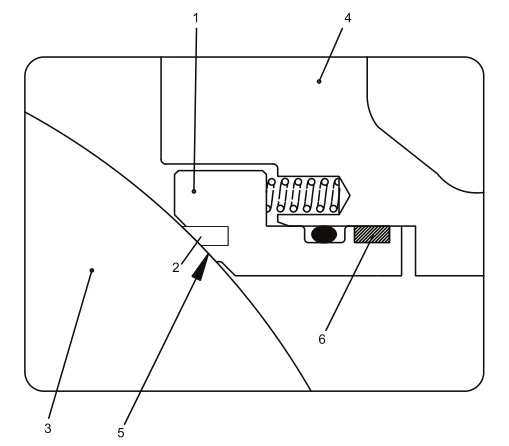
When a fire-tested ball valve is required, or when the purchaser specifies fire-tested valves, the valve design supplied shall have successfully passed API 607. See Figure 2 for two examples of a fire-resistant seat arrangement using a resilient primary non-fire-resistant seal and a secondary metal back-up seat.
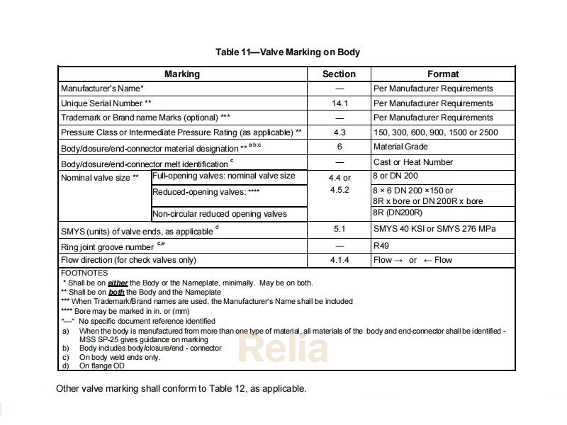
8 Marking
8.1 Identification plate shall be marked in accordance with ASME B1 6.34 and shall also be marked “API 608.”
8.2 Body end flanges require marking when end flanges are ring type joint design. The ring joint groove number (such as R24) shall be marked on each end flange outside diameter using low-stress marking. Ring joint groove numbers are as shown in ASME B16.5.
8.3 The following indicate special marking for unidirectional valves.
8.3.1 Valves designed for or modified to have sealing capability in only one direction or orientation shall be marked to identify the unidirectional seat. Markings shall be applied to the body of the valve at the appropriate end or on an identification plate (see 6.5).
8.3.2 Markings on the body shall consist of letters or symbols cast, stamped, or otherwise integral with the valve, or marked on an identification plate (see 6.5), or both. When stamping is used on valve body, low-stress stamping process shall be used.
8.3.3 Typical markings include arrows to indicate preferred sealing direction or “high-pressure side” marked at the appropriate end connection or on the identification plate (see Figure 3).
9 Packaging and Shipping Requirements
9.1 Prior to packaging or shipping, each valve shall be drained of test fluid, including draining of the body cavity area between seats and around ball and cavities of “cored balls” if used.
9.2 Valves manufactured with shell materials shown in ASME B1 6.34 Group 1 shall have lead-free rust preventative coatings on all unmachined exterior body surfaces.
9.3 Machined or threaded surfaces that are not protected from atmospheric corrosion shall be coated with an easily removable, lead-free rust inhibitor.
9.4 Protective end plugs of wood, wood fiber, plastic, or metal shall be securely inserted into the valve end connections of socket-welding and threaded valves or over the threaded ends in the case of external threaded ends.
The protective end plugs or covers shall be of a design such that the valve cannot be installed with the protective plug or cover in place.
9.5 Protective covers of wood, wood fiber, plastic, or metal shall be securely attached to the valve ends of flanged and butt-welding end valves to protect the gasket surfaces and weld end preparations. The protective end covers shall be of a design such that the valve cannot be installed with the protective cover in place.
9.6 At the time of shipment, the ball shall be in the full open position, unless design precludes this position, such as in the case of a spring-return to closed position actuated ball valve.
9.7 Tapped auxiliary connections shall be fitted with fully tightened solid threaded plugs (see 5.3.9 and 6.6). The thread sealant used to seal the plugs shall be suitable for the full pressure and temperature rating of the valve or as per agreement between purchaser and valve manufacturer.
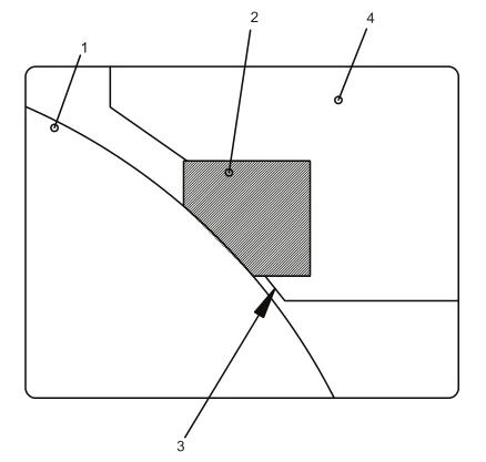
Key
1 ball
2 seat
3 secondary metal sealing
4 adapter or body
a) Fire-resistant Seat Arrangement—Floating Ball Valve
Key
1 seat holder
2 seat
3 ball
4 adapter or body
5 secondary metal seat
for fire safety
6 graphite back-up ring
b) Fire-resistant Seat Arrangement—Trunnion Ball Valve
Figure 2—Typical Fire-resistant Seats
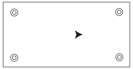
Figure 3—Typical Unidirectional Valve Identification Plate Symbol
9.8 Valves shall be packaged to prevent damage during shipment.
9.9 When export packaging is specified in purchase order, valves shall be shipped in wooden boxes or crates and packed to prevent individual valves from moving within the crate or box.
10 Spare Parts
When specified on the purchase order, manufacturer shall submit a complete list of recommended spare parts. This list shall include cross-sectional assembly drawings for identification of recommended spare parts and part numbers.
Annex B
(informative)
Figures
Key
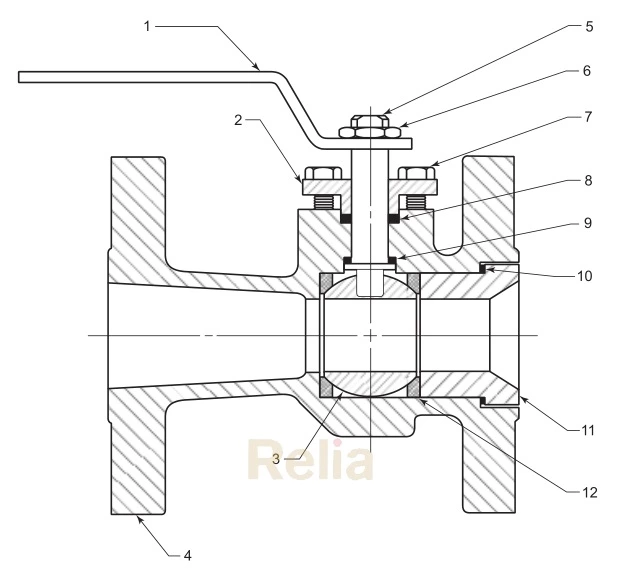
1 handle (lever type)
2 gland flange
3 ball
4 body
5 stem
6 stem nut
7 gland bolting
8 stem seal
9 thrust washer
10 body seal
11 body insert
12 seat
Figure B.1—Typical Floating Ball Valve Components (One-piece Body/Unibody Illustrated)—Nomenclature
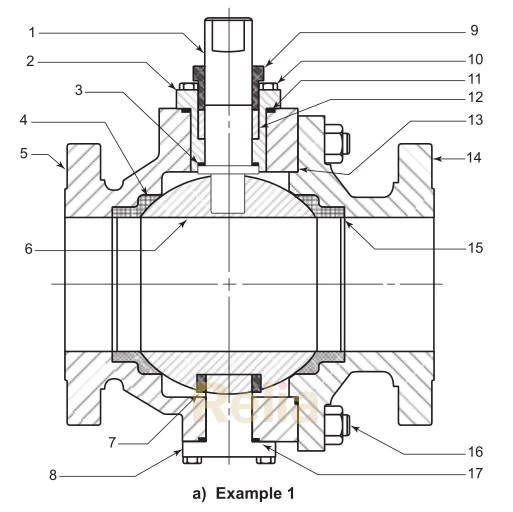
Cast steel trunnion ball valve
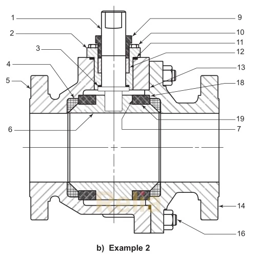
Forged steel trunnion ball valve
Key
1 stem
2 cover
3 thrust washer
4 seat
5 body
6 ball
7 trunnion bearing
8 trunnion
9 gland
10 cover bolting
11 cover seal
12 stem seal
13 body seal
14 body cap
15 seat spring
16 body bolting
17 trunnion seal
18 trunnion plate
19 bearing spacer
Figure B.2—Typical Trunnion-mounted Ball Valve Components (Split-body Valve Illustrated)—Nomenclature