API 607: Fire Test for Quarter-turn Valves
API 607 standard specifies fire type-testing requirements and a fire type-test method for confirming the pressure-containing capability of quarter-turn valves and other valves with nonmetallic seating under pressure during and after the fire test.
1 Scope
This standard specifies fire type-testing requirements and a fire type-test method for confirming the pressure-containing capability of quarter-turn valves and other valves with nonmetallic seating under pressure during and after the fire test. It does not cover the testing requirements for valve actuators other than manually operated gear boxes or similar mechanisms when these form part of the normal valve assembly. Other types of valve actuators(e. g. electrical, pneumatic, or hydraulic)may need special protection to operate in the environment considered in this valve test, and the fire testing of such actuators is outside the scope of this standard.
NOTE For the purposes of this standard, the terms "fire type-test"and "fire test"are synonymous.
4 Test Conditions
4. 1 Direction and Conditions for Valves to Be Tested
4. 1. 1 Symmetric seated valves intended by the manufacturer for bidirectional installationshall be tested in one direction only.
4. 1. 2 Asymmetric seated valves intended by the manufacturer for bidirectional installationshall be tested by carrying out the burn test procedure twice, once in each direction of the potential installation. The same valve may be refurbished and re-tested, or another, identical, valve may be tested in the other direction.
4. 1. 3 Valves intended solely for unidirectional installation shall be clearly and permanently marked as such and shall be tested in the stated direction of installation.
4. 1. 4 If the valve being tested is fitted with a gearbox or other such manual device, then only that particular assembly shall qualify. If a valve can be supplied with or without a gearbox, testing with a gearbox fitted shall qualify valves without a gearbox but not the converse. Grease may be removed from a gearbox prior to testing for safety purposes.
4. 1. 5 Valves(and gearboxes)shall not be protected with insulation material of any form during testing, except where such protection is part of the design of the component(s).
4. 1. 6 Prior to initiating the test, inspection requirements and testing by the valve manufacturer shall have been completed on the valve in accordance with API Standard 598 or applicable production testing.
4. 2 Pressure Relief Provision
lf the valve under test incorporates a pressure relief device as part of its standard design and if this device activates during the fire test, then the test shall be continued and any leakage to atmosphere from the deviceshall be measured and counted as external leakage. If the design is such that the device vents to the downstream side of the valve, then any leakageshall be counted as through-seat leakage (see 5. 6. 12 and 5. 6. 14). However, the test shall be stopped if the system pressure relief device described in 5. 3. 2. 8 activates.
5 FireTest Method
5. 1 General Warning
Fire testing of valves is potentially hazardous, and it is essential that the safety of personnel be given prime consideration. Given the nature of the fire test and the possibility of weaknesses in the design of the test valve and test equipment, hazardous rupture of the pressure boundary could occur. Adequate shields in the area of the test enclosure and other appropriate means for the protection of personnel are necessary.
5. 2 Principle
A closed valve completely filled with water under pressure is completely enveloped in flames with an environmental temperature in the region of the valve of 750 ℃ to 1000 ℃ (1400 F to 1800 °F)for a period of 30 minutes. The objective is to completely envelop the valve in flames to ensure that the seat and sealing areas are exposed to the high burn temperature. The intensity of the heat inputshall be monitored using thermocouples and calorimeter cubes as specified in 5. 6. 9 and 5. 6. 10. During this period, the internal and external leakage is recorded. After cool-down from the fire test, the valve is tested to assess the pressure-containing capability of the valve shell, seats, and seals.
5. 3 Apparatus
5. 3. 1 General
The test equipment shall not subject the valve to externally applied stress affecting the results of the test. Schematic diagrams of recommended systems for fire type-testing of valves are given in Figure 1. Potential pipework-to-valve end connection joint leakage is not evaluated as part of the test and is not included in the allowable external leakage (see 6. 3 and 6. 6). For the purposes of this test, it may be necessary to modify these joints to eliminate leakage. The test equipment shall be designed so that if the nominal diameter of the pipework situated immediately upstream of the test valve is larger than DN 25 or one-half the DN of the test valve, the pipework shall be enveloped in flames for a minimum distance of 150 mm (6 in. )from the test valve. The diameter of the upstream pipe work shall be sufficient to deliver a flow rate in excess of the maximum allowable leak rate for the size of the valve being tested. The pipework downstream of the test valveshall be at least DN 15 and shall be inclined so that the downstream side is fully drained. The flame source shall be at least 150 mm (6 in. )minimum away from the valve or any calorimeters and should have sufficient capacity to completely envelop the valve in flames. The enclosure containing the valve shall provide a horizontal clearance of a minimum of 150 mm (6 in. ) between any part of the test valve and the enclosure, and the height of the enclosure above the top of the test valve shall be a minimum of 150 mm (6 in. ).
5. 3. 2 Specific Apparatus
5. 3. 2. 1 Vapor trap to minimize the cooling effect of the upstream liquid. See Figure 1, (8).
5. 3. 2. 2 Industrial pressure measurement devices having a full- scale reading of between 1. 5 and 4 times the pressure being measured. The accuracy of each test device used at any point on the scaleshall be within 3 %of its maximum scale value for readings taken both up and down the scale with either increasing or decreasing pressure. See Figure 1, (7)(14).
5. 3. 2. 3 Calorimeter cubes made of carbon steel in accordance with the design and dimensions shown in Figure 2, with a thermocouple of the accuracy specified in 5. 3. 2. 4 , located in the center of each cube. Calorimeter cubes shall be scale free before exposure to the fire environment.
5. 3. 2. 4 Flame environment and valve body thermo couples of an accuracy at least equal to tolerance class 2 for type B or tolerance class 3 for other types as specified in IEC 60584-2. See Figure 1, (13).
5. 3. 2. 5 Containers of a size suitable for collecting the water leaked from the valve under test. See Figure 1, (18).
5. 3. 2. 6 Calibrated sight gauge or device for measuring the water used during the test. See Figure 1, (4).
5. 3. 2. 7 Calibrated device for measuring the leakage water collected during the test.
5. 3. 2. 8 Pressure relief provision, incorporated in the system, consisting of a pressure relief valve to relieve the test valve center cavity pressure to the atmosphere, to protect against potential rupture of the valve if it is designed such that liquid can be trapped in the cavity. See Figure 1, (14). The pressure relief valve settingshall be either a)that determined by the valve manufacturer from data obtained by hydrostatic pressure testing of valves of the same size and type as the fire-tested valve or b)when pressure test data are not available, a seting not greater than 1. 5 times the maximum allowable working pressure at 20 ℃(70 F). The maximum allowable working pressure depends on materials, design, and working temperatures and is to be selected from the tables of pressure-temperature ratings given in the appropriate standards such as ASME B16. 34.
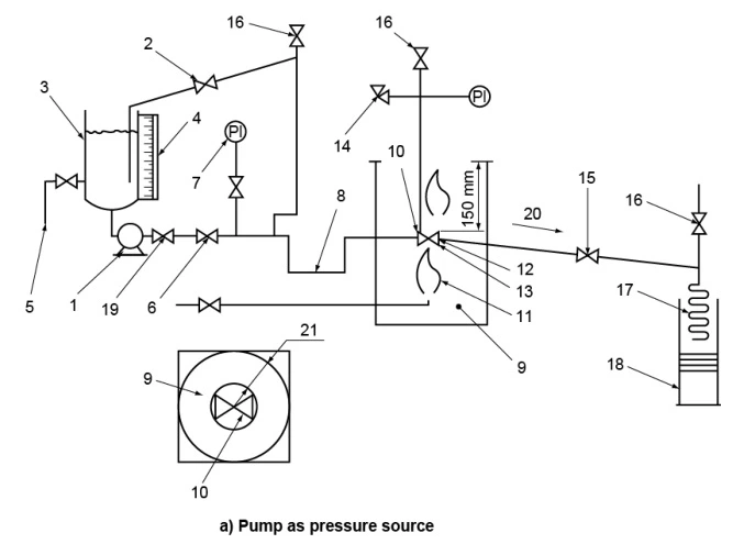
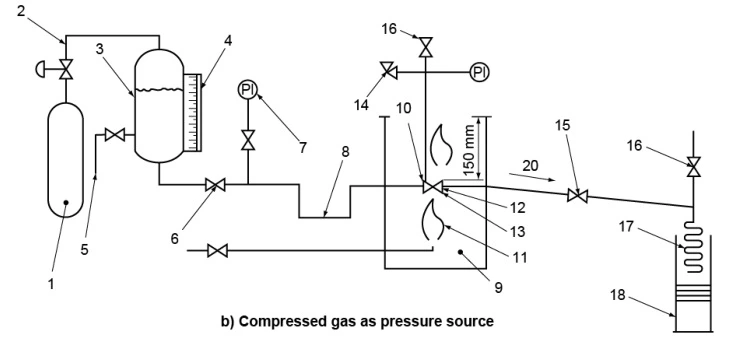
Figure 1—Recommended Systems
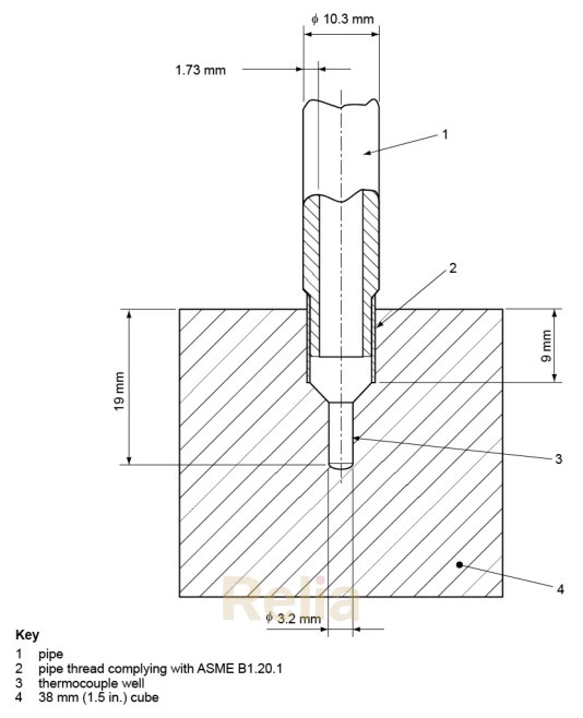
Figure 2—Calorimeter Cube Design and Dimensions
5. 4 Test Fluid
The test fluid used shall be water.
5. 5 Test Fuel
The test fuelshall be gaseous.
5. 6 Procedure
NOTE The numbered items in parentheses refer to the apparatus of Figure 1
5. 6. 1 Mount the test valve in the test apparatus so that the stem and bore of the valve are in the horizontal position. Mount a valve that operates in only one direction (unidirectional)in their normal operating position. Locate the flame environment, body thermocouples, and calorimeter cubes in the positions shown in Figures 3 and 4, as appropriate. For nonmetallic seated valves up to DN 100 or NPS 4 and pressure ratings up to Class 300, use two flame environment thermocouples and two body thermocouples and calorimeter cubes as shown in Figure 3. For all other valves, use two flame environment thermocouples and two calorimeter cubes as shown in Figure 4. For valves DN 200 or NPS 8 and larger, use the third calorimeter cubes as shown in Figure 4.
5. 6. 2 With the test valve in the partially open position, open the water supply valve (5), the shut-off valve (6), the vent valves (16), and the shut-off valve(15)to flood the system and purge the air. When the system is completely filled with water, close the shut-off valve (15), the vent valves (16), and the water supply valve (5). Pressurize the system with water to a test pressure of 1. 4 times the maximum allowable working pressure at 20 ℃ (70 F)—the actual test pressure may be rounded up to the next highest bar'. Check for leaks in the test apparatus and eliminate as necessary. Release the pressure, close the test valve, and open the shut-off valve (15).
5. 6. 3 If the valve under test is of the upstream sealing type, determine the volume of water that is trapped between the upstream seat sealand the downstream seat seal when the valve is closed. Record this volume. It is assumed that, during the fire type-test, this volume of water will flow through the valve and pass the downstream seat seal to be collected in the container (18). Since this volume has not actually leaked through the upstream seat seal, it is deducted from the total volume collected in the downstream container when determining the through-seat leakage (see 5. 6. 11).
5. 6. 4 Pressurize the system to one or the other of the following pressures, as appropriate:
a)for nonmetallic seated valves rated Class 150 and Class 300, the low test pressure at 0. 2 MPa(30 psig);
b)for all other valves, the high test pressure at 75 %of the maximum permissible seat working pressure at 20 ℃ (70°F). Maintain this test pressure during the burn and cool- down periods, momentary pressure losses of up to 50 %of the test pressure being permitted provided that the pressure recovers within 2 minutes and the cumulative duration is less than 2 minutes.
5. 6. 5 Record the reading on the calibrated sight gauge or device (4). Empty the container (18).
5. 6. 6 Adjust the test system, excluding the test valve, during the test period to maintain the temperatures and pressures required.
5. 6. 7 Open the fuel supply, establish a fire, and monitor the flame environment temperature throughout the burn period of 30 minutes, +5, -0 minutes. Check that the average temperature of the two flame environment thermocouples (13)reaches 750 ℃(1400 F)within 2 minutes from the start of the burn period, i. e. from ignition of the burners. Maintain the average temperature between 750 C and 1000 ℃(1400 F to 1800 F), with no reading less than 700 ℃(1300 F)for the remainder of the burn period of 30 minutes.
5. 6. 8 If cavity pressure exceeds the stated manufacturer's allowable pressure, the test shall end and be reported as an invalid test.
5. 6. 9 The average temperature of the calorimeter cubes shall be 650 ℃(1200 F)within 15 minutes of starting the burn period. For the remainder of the burn period, maintain the minimum average temperature of 650 ℃ (1200 F), with no temperature falling to less than 560 ℃(1000 °F). For valves subjected to the low-pressure test (see 5. 6. 4), the body thermocouple shall maintain 590 ℃(1100 F)for at least 5 minutes and the bonnet thermocouple shall maintain 650 ℃(1200 °F)for at least 15 minutes of the burn period. The burn period may be extended by up to 5 minutes in order to achieve this requirement.
5. 6. 10 Record instrument readings (7), (12), (13), (14)every 30 seconds during the burn period. Thermocouples should be numbered, and individual records of temperatureshall be recorded.
5. 6. 11 At the end of the burn period (30 minutes, +5, -0 minutes), shut off the fuel supply.
5. 6. 12 Immediately determine the amount of water collected in the container(18)and establish the total through-seat leakage during the burn period. If the test valve is an upstream sealing type (see 5. 6. 3), deduct the volume of water trapped between the upstream seat sealand the downstream seat seal. Continue collecting water in the container (18)for use in establishing the external leakage rate of the test valve during the burn and cool-down periods.
5. 6. 13 Within 5 minutes of extinguishing the fire, force-cool the test valve with water so that its external surface temperature remains below 100 ℃ (212 °F);the time for cooling shall not exceed 10 minutes. Record the time taken to force- cool the external surface of the valve below 100 ℃ (212 F).
Warning—The internal parts of the valve could remain at significantly higher temperatures than the external surface of the valve.
5. 6. 14 Check and adjust the test pressure in accordance with 5. 6. 4. Record the readings on the sight gauge (4) and determine the quantity of water in the container (18). Record any leakage through the external pressure relief device if fitted as part of the standard design. The figures are used to calculate the total external leakage throughout the burn and cool-down periods.
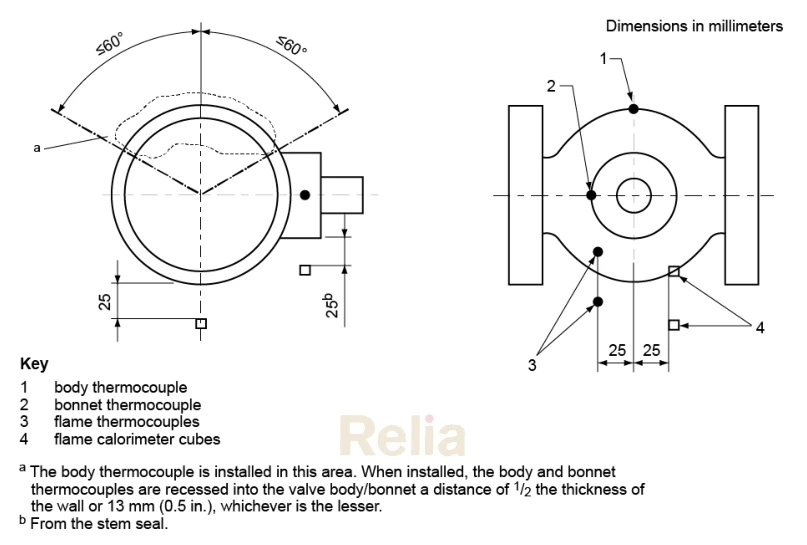
Figure 3—Location of Temperature Measurement Sensors—
Nonmetallic Seated Valves up to DN 100, NPS 4, Class 150 and Class 300
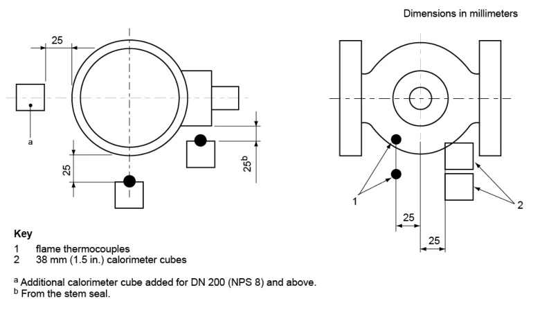
Figure 4—Location of Temperature Measurement Sensors for All Other Valves
(Nonmetallic Seated Valves Larger Than DN 100, NPS 4, Class 150 and Class 300, and All Valve Sizes Class 300)
5. 6. 15 For valves Class 600 and lower, decrease or stabilize the pressure to the low test pressure at 0. 2 MPa (30 psig)and measure the through-seat leakage over a 5-minute period.
5. 6. 16 Increase or stabilize the test pressure to the high test pressure, close the shut-off valve(15), and operate the test valve against the test pressure to the fully open position.
5. 6. 17 Stabilize the pressure to the high test pressure and measure the external leakage over a 5-minute period.
6 Performance
6. 1 General
Valves tested in accordance with 5 shall be in accordance with 6. 2 to 6. 7.
6. 2 Through-seatLeakageDuringBurn Period
For the low-pressure test, the average through-seat leakage at low test pressure during the burn period (see 5. 6. 11)shall not exceed the value given in Table 1. For the high-pressure test, the average through-seat leakage at high test pressure during the burn period (see 5. 6. 11)shall not exceed the value given in Table 1.
6. 3 External Leakage During Burn and Cool-down Periods
For the low-pressure test, the average external leakage, not including through-seat leakage, during the burn and cool-down periods(see 5. 6. 13)shall not exceed the value given in Table 1. For the high-pressure test the average external leakage, not including through-seat leakage, during the burn and cool-down periods(see 5. 6. 13)shall not exceed the value given in Table 1.
6. 4 Low-pressure Test Through-seat Leakage After Cool- down
The maximum through-seat leakageshall not exceed the value given in Table 1.
6. 5 Operability
After the completion of fire testing, the operability of the valveshall be checked. While the valve is in the closed position, the full test pressure (5. 6. 4)shall be applied against the closure member. The valveshall be cycled from the fully closed to the fully open position using the operator fitted to the test valve. Due to the temperature of the test, high pressures within the valve may be at a level that may compromise the pressure boundary integrity. Extension handles are allowed to protect the operating personnel from risks associated with potential loss of containment during the valve operation. The use of extension handles shall not result in an applied torque that is higher than that available from the fitted operator.
6. 6 External LeakageFollowing Operational Test
The average external leakage of the valve in the open position at the high test pressure (see 5. 6. 16)shall not exceed the value given in Table 1.
Table 1—Maximum Leak Rates All leakage in ml/min
| Size | Through-seat Leakage | External Leakage | |||||
| DN | NPS | During Burn (See 5. 6. 11 and 6. 2) | After Cooldown (See 5. 6. 15 and 6. 4) |
During Burn and Cooldown (See 5. 6. 13 and 6. 3) |
After Operational Test (See 5. 6. 17 and 6. 6) | ||
| Low Pressure Test | High Pressure Test | Low Pressure Test | Low Pressure Test | High Pressure Test | High Pressure Test | ||
| 8 | /4 | 32 | 128 | 13 | 8 | 32 | 8 |
| 10 | 3/8 | 40 | 160 | 16 | 10 | 40 | 10 |
| 15 | /2 | 60 | 240 | 24 | 15 | 60 | 15 |
| 20 | 3/4 | 80 | 320 | 32 | 20 | 80 | 20 |
| 25 | 1 | 100 | 400 | 40 | 25 | 100 | 25 |
| 32 | 1'/4 | 128 | 512 | 51 | 32 | 128 | 32 |
| 40 | 11/2 | 160 | 640 | 64 | 40 | 160 | 40 |
| 50 | 2 | 200 | 800 | 80 | 50 | 200 | 50 |
| 65 | 2'/2 | 260 | 1040 | 104 | 65 | 260 | 65 |
| 80 | 3 | 320 | 1280 | 128 | 80 | 320 | 80 |
| 100 | 4 | 400 | 1600 | 160 | 100 | 400 | 100 |
| 125 | 5 | 500 | 2000 | 200 | 125 | 500 | 125 |
| 150 | 6 | 600 | 2400 | 240 | 150 | 600 | 150 |
| 200 | 8 | 800 | 3200 | 320 | 200 | 800 | 200 |
| >200 | >8 | 800 | 3200 | 320 | 200 | 800 | 200 |
NOTE External leakage does not include potential leakage from the pipework-to-valve end connection (see 5. 3. 1).
7 Qualification of Other Valves by Representative Size, Pressure Rating, and Materials of Construction
7. 1 General
Instead of testing each nominal size and nominal pressure rating of a given valve design, all valves of the same basic design(type, model, and/or configuration), as the test valve, may be deemed to have been fire-tested, subject to the following limitations.
a) A test valve may be used to qualify valves larger than the test valve but not exceeding twice the nominal size of the test valve (see 7. 3). A size DN 200 or NPS 8 test valve qualifies all larger sizes. If the minimum size of a given range of valves is greater than DN 200 or NPS 8, then the minimum size of the range shall be tested to qualify all sizes.
b) A DN 50(NPS 2)valve may be used to qualify all smaller sizes of valve of the same types. If the maximum size of a given range of valves is smaller than DN 50 or NPS 2, then the maximum size of the range shall be tested to qualify all sizes.
c) A test valve may be used to qualify valves with higher Class ratings but not exceeding twice the Class rating of the test valve, except as shown in Tables 3 and 4.
d) A reduced bore(or Venturi pattern)test valve may be used to qualify a smaller nominal size full bore (or regular pattern)valve when the components associated with the obturator, seat seals, and stem are identical in design and size. In such a case, the permissible average leakage rates are those applicable to the full bore (or regular pattern)valve.
e) The type of valve body ends is not considered by this standard. However, the mass of the valve is determined in part by the body end type. For qualification to the present standard, and providing that all other qualification criteria have been met, valves with ends different to those of the test valve may also qualify provided that their mass is greater than that of the test valve or their mass is not less than 75 %of that of the test valve.
7. 2 Materials of Construction
7. 2. 1 For the purposes of product compliance certification or type testing systems, the materials of construction of the pressure-retaining envelope of the valve shall be deemed to qualify other materials of construction within the generic classifications below:
一 ferritic,
— austenitic
一 duplex.
7. 2. 3 If a range of valves is covered by testing of ferritic test valves then the type-testing coverage may be extended to cover austenitic or duplex materials by carrying out a further test on a single valve of each material. For product lines NPS 2 and below, the valveshall be of the maximum size of the product range. For those where the product line extends to larger sizes, the valveshall be equal to or greater than the median size in the ferritic testing. Other materials of construction of the pressure-retaining envelope of the valve require full testing of representative size and pressure ratings as specified in 7. 3 and 7. 4.
7. 2. 4 Alloy steel bolting(e. g. B7, L7)used as part of the valve's pressure-retaining envelope may be used to qualify austenitic steel bolting but not vice versa.
7. 2. 5 Any change in nonmetallic materials with respect to the seat- to-closure member seal, seat-to-body seal, stem seal, and body joint seal require a re- qualification. Filled PTFE, however, may qualify non-filled PTFE and vice versa.
7. 3 Qualification of Valves by Nominal Size
The valves of other nominal sizes that may be deemed to have been fire type-tested relative to the actual valve tested are given in Tables 2 and 3.
7. 4 Qualification of Valves byPressure Rating
The valves of other Classes that may be deemed to have been fire type-tested relative to the actual valve tested are given in Table 4.
Table 2—Other Valves Qualified by DN
| Size of Valve to Be Tested DN | Other Valve Sizes Qualified DN |
| 50 | 50 and below; 65; 80; 100 |
| 65 | 65; 80; 100; 125 |
| 80 | 80; 100; 125; 150 |
| 100 | 100; 125; 150; 200 |
| 125 | 125; 150; 200; 250 |
| 150 | 150; 200; 250; 300 |
| 200 | 200 and larger |
Table 3—Other Valves Qualified by NPS
| Size of Valve to Be Tested NPS | Other Valve Sizes Qualified NPS |
| 2 | 2 and below;21/2;3;4 |
| 2¹/2 | 21/2:3:4;5 |
| 3 | 3;4;5;6 |
| 4 | 4;5;6;8 |
| 5 | 5;6;8;10 |
| 6 | 6;8;10;12 |
| 8 | 8 and larger |
Table 4—Other Valves Qualified by Class
| Valve Tested Class Rating | Other Valves Qualified |
| Class Rating | |
| 150 | 150; 300 |
| 300 | 300; 400; 600 |
| 400 | 400; 600; 800 |
| 600 | 600; 800; 900 |
| 800 | 800; 900; 1500 |
| 900 | 900; 1500 |
| 1500 | 1500; 2500 |
| 2500 | 2500 |