API 603 Minimum Thickness of Shell Wall
Table 1—Minimum Thickness of Shell Wall and Minimum Diameter of Stem,tm
| Nominal Size DN | Class 150 | Class 300 | Class 600 | Nominal Size NPS | |||
| Shell Wall Thickness mm(in.) | Stem Diameter mm(in.) | Shell Wall Thickness mm (in.) | Stem Diameter mm(in.) | Shell Wall Thickness mm(in.) | Stem Diameter mm(in.) | ||
| 15 | 3.2 (0.12) | 10.7 (0.42) | 3.3 (0.13) | 12.3 (0.48) | 3.6 (0.14) | 12.3 (0.48) | 1/2 |
| 20 | 3.6 (0.14) | 10.7 (0.42) | 3.8 (0.15) | 12.3 (0.48) | 4.2 (0.16) | 12.3 (0.48) | 3/4 |
| 25 | 4.0 (0.16) | 12.3(0.48 | 4.3 (0.17) | 15.5 (0.61) | 4.8 (0.19) | 15.5 (0.61) | |
| 32 | 4.4 (0.17) | 12.3 (0.48) | 4.8 (0.19) | 15.5 (0.61) | 5.1 (0.20 | 15.5 (0.61) | 11/4 |
| 40 | 4.8 (0.19) | 13.9 (0.55) | 5.2 (0.21) | 18.7 (0.73) | 5.5(0.22 | 18.7 (0.73) | 11/2 |
| 50 | 5.5(0.22) | 15.5 (0.61) | 6.1 (0.24) | 18.7 (0.73) | 6.2 (0.25) | 18.7 (0.73) | 2 |
| 65 | 5.8 (0.23) | 15.5(0.61 | 6.5 (0.26 | 18.7 (0.73 | 7.1 (0.28) | 21.8 (0.86) | 21/2 |
| 80 | 6.0 (0.24) | 18.7 (0.73) | 6.9 (0.28) | 21.8 (0.86) | 7.9 (0.31) | 25.0 (0.98) | 3 |
| 100 | 6.4 (0.26) | 21.8(0.86) | 7.8 (0.31) | 25.0 (0.98) | 9.6 (0.38) | 28.2 (1.11) | 4 |
| 150 | 7.2 (0.28) | 25.0 (0.98) | 9.4 (0.38) | 31.3 (1.23) | 13.1 (0.52) | 37.6(1.48) | 6 |
| 200 | 8.0 (0.32) | 28.2 (1.11) | 11.1 (0.44) | 34.4 (1.35) | 16.3 (0.64) | 40.7(1.60) | 8 |
| 250 | 8.8 (0.35) | 31.3 (1.23) | 12.8 (0.51) | 37.6(1.48) | 19.5 (0.77) | 46.9(1.84) | 10 |
| 300 | 9.7 (0.38) | 34.4(1.35) | 14.5(0.58) | 40.7 (1.60) | 22.9(0.90) | 50.1 (1.97) | 12 |
| 350 | 10.2 (0.40) | 40.7 (1.60) | 15.5(0.62) | 43.8 (1.72) | 24.9(0.98) | 56.4 (2.22) | 14 |
| 400 | 11.0 (0.43) | 43.8 (1.72) | 17.2 (0.68) | 46.9(1.84) | 28.1 (1.11) | 59.5(2.34 | 16 |
| 450 | 11.8(0.47 | 46.9(1.84 | 18.6(0.74 | 50.1(1.97) | 31.1 (1.22) | 62.7 (2.47) | 18 |
| 500 | 12.7 (0.50) | 50.1 (1.97) | 20.3 (0.81) | 53.3 (2.09) | 34.1 (1.34) | 69.1 (2.72) | 20 |
| 600 | 14.3 (0.56) | 56.4 (2.22) | 23.7 (0.94) | 62.7 (2.47) | 40.5(1.60) | 75.4 (2.97) | 24 |
| NOTE 1 See 5.8.1 and 5.8.3. NOTE 2 Wall thickness calculated from equation of ASME B16.34 Appendix VI,with minimum flow diameter (d)per Table A-1 of ASME B16.34 for applicable valve DN or NPS and pressure class. | |||||||
5 Design
5.1 General
5.1.1 A valve body schematic is shown as Figure 1. The minimum body wall thickness, t m , at the time of manufacture shall be as given in Table 1, except as indicated in 5.1.2 for butt-welding valve ends. Additional metal thickness needed for assembly stresses, stress concentrations, and shapes other than circular shall be determined by individual manufacturers.
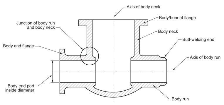
Figure 1—Identification of Terms
5.1.2 The weld end preparation in butt-welding end valves (see 5.3.2)shall not reduce the body wall thickness to less than the values specified in 5.1.1 within a region closer than tm to the outside surface of the body neck,measured along the run direction.The transition to the weld preparation shall be gradual and the section shall be essentially circular through the entire length of the transition.Sharp discontinuities or abrupt changes in section in areas that infringe into the transition shall be avoided,except that test collars or bands,either welded or integral,are allowed.In no case shall the thickness be less than 0.77 tm at a distance of 2 tm from the weld end.
5.2 Bonnet Wall Thickness
The minimum bonnet wall thickness at the time of manufacture,except for the neck extension that contains the packing, shall be tm as given in Table 1.For the neck extension,the local minimum wall thickness shall be based on the local diameter,e.g.the inside diameter of the stem bore or packing box bore,and shall be in accordance with valve body neck rules of para.6.1.3 of ASME B16.34.