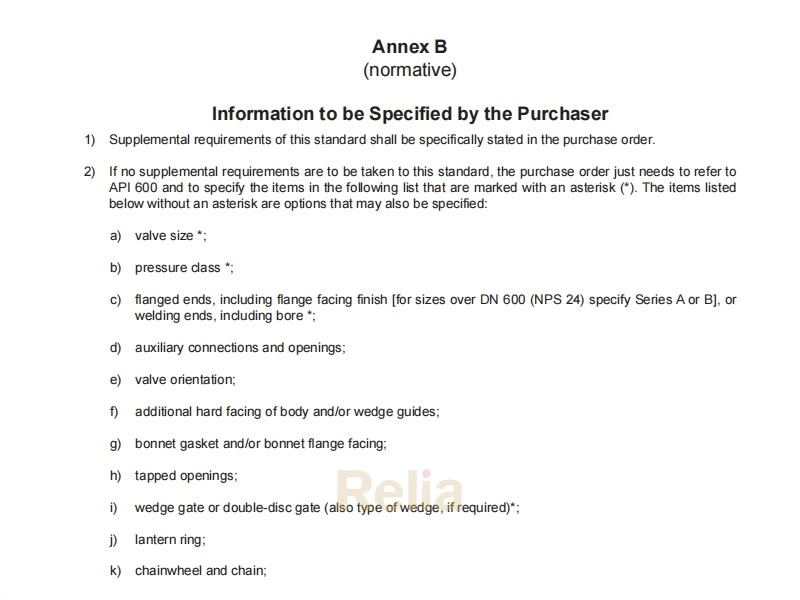
API 600 Design Requirement, Wall Thickness, Minimum Inside Diameter
API 600 gate valve design requirement, including body wall thickness, minimum inside diameter, minimum wear travel and maximum stem projection, minimum stem diameter, and permitted undertolerance etc.
5 Design
5.1 Body Wall Thickness
5.1.1 A valve body schematic is shown in Figure 1. The minimum body wall thickness, tm, at the time of manufacture shall be as given in Table 1, except as indicated in 5.1.2 for butt-welding valve ends. Additional metal thickness needed for assembly stresses, stress concentrations, and shapes other than circular shall be determined by individual manufacturers, since these factors vary widely.
5.1.2The weld end preparation in butt-welding end valves (see 5.3.2) shall not reduce the body wall thickness to less than the values specified in 5.1.1 within a region closer than tm to the outside surface of the body neck, measured along the run direction. The transition to the weld preparation shall be gradual and the section shall be essentially circular through the entire length of the transition. Sharp discontinuities or abrupt changes in section in areas that infringe into the transition shall be avoided, except that test collars or bands, either welded or integral, are allowed. In no case shall the thickness be less than 0.77tm at a distance of 2tm from the weld end.
5.2 Bonnet Wall Thickness
The minimum bonnet wall thickness at the time of manufacture, except for the neck extension that contains the packing, shall be tm as given in Table 1. For the neck extension, the local minimum wall thickness shall be based on the local diameter, e.g., the inside diameter of the stem bore or packing box bore, and shall be in accordance with the valve body neck rules of ASME B16.34.
5.3 Body Dimensions
5.3.1Flanged Ends
5.3.1.1 Body end flanges shall comply with the dimensional requirements of ASME B16.5 for sizes up to and including DN 600 (NPS 24). For sizes over DN 600 (NPS 24), body end flanges shall comply with the dimensional requirements of ASME B16.47 Series A or Series B as specified by the purchaser. Unless otherwise specified, raised face end flanges shall be provided. The purchaser may specify a flange facing finish other than that specified in ASME B16.5 or ASME B16.47, as applicable.
5.3.1.2 Face-to-face dimensions shall be in accordance with ASME B16.10 or ISO 5752. For sizes not listed, dimensions shall be as agreed to between purchaser and manufacturer. Body end flanges and bonnet flanges shall be cast or forged integral with the body. However, flanges may be attached by welding when approved by the purchaser.
Table 1—Minimum Wall Thickness for Body and Bonnet
| Class Designation | 150 | 300 | 600 | 900 | 1500 | 2500 | Class Designation |
| Nominal Size DN | Minimum Wall Thickness tm mm (in.) | Nominal Pipe Size NPS | |||||
| 25 | 6.4 (0.25) | 6.4 (0.25) | 7.9 (0.31) | 12.7 (0.50)a | 12.7 (0.50) | 15.0 (0.59) | 1 |
| 32 | 6.4 (0.25) | 6.4 (0.25) | 8.6 (0.34) | 14.2 (0.56) a | 14.2 (0.56) | 17.5 (0.69) | 1 1/4 |
| 40 | 6.4 (0.25) | 7.9 (0.31) | 9.4 (0.37) | 15.0 (0.59) a | 15.0 (0.59) | 19.1 (0.75) | 1 1/2 |
| 50 | 8.6 (0.34) | 9.7 (0.38) | 11.2 (0.44) | 19.1 (0.75) a | 19.1 (0.75) | 22.4 (0.88) | 2 |
| 65 | 9.7 (0.38) | 11.2 (0.44) | 11.9 (0.47) | 22.4 (0.88) a | 22.4 (0.88) | 25.4 (1.00) | 2 1/2 |
| 80 | 10.4 (0.41) | 11.9 (0.47) | 12.7 (0.50) | 19.1 (0.75) | 23.9 (0.94) | 30.2 (1.19) | 3 |
| 100 | 11.2 (0.44) | 12.7 (0.50) | 16.0 (0.63) | 21.3 (0.84) | 28.7 (1.13) | 35.8 (1.41) | 4 |
| 150 | 11.9 (0.47) | 16.0 (0.63) | 19.1 (0.75) | 26.2 (1.03) | 38.1 (1.50) | 48.5 (1.91) | 6 |
| 200 | 12.7 (0.50) | 17.5 (0.69) | 25.4 (1.00) | 31.8 (1.25) | 47.8 (1.88) | 62.0 (2.44) | 8 |
| 250 | 14.2 (0.56) | 19.1 (0.75) | 28.7 (1.13) | 36.6 (1.44) | 57.2 (2.25) | 67.6 (2.66) | 10 |
| 300 | 16.0 (0.63) | 20.6 (0.81) | 31.8 (1.25) | 42.2 (1.66) | 66.8 (2.63) | 86.6 (3.41) | 12 |
| 350 | 16.8 (0.66) | 22.4 (0.88) | 35.1 (1.38) | 46.0 (1.81) | 69.9 (2.75) | -- | 14 |
| 400 | 17.5 (0.69) | 23.9 (0.94) | 38.1 (1.50) | 52.3 (2.06) | 79.5 (3.13) | -- | 16 |
| 450 | 18.3 (0.72) | 25.4 (1.00) | 41.4 (1.63) | 57.2 (2.25) | 88.9 (3.50) | -- | 18 |
| 500 | 19.1 (0.75) | 26.9 (1.06) | 44.5 (1.75) | 63.5 (2.50) | 98.6 (3.88) | -- | 20 |
| 600 | 20.6 (0.81) | 30.2 (1.19) | 50.8 (2.00) | 73.2 (2.88) | 114.3 (4.50) | -- | 24 |
| 650 | 21.4 (0.84) | 31.6 (1.24) | ── | ── | ── | ── | 26 |
| 700 | 22.2 (0.87) | 33.3 (1.31) | ── | ── | ── | ── | 28 |
| 750 | 23.0 (0.91) | 34.9 (1.37) | ── | ── | ── | ── | 30 |
| 800 | 23.8 (0.94) | 36.0 (1.41) | ── | ── | ── | ── | 32 |
| 850 | 24.6 (0.97) | 38.1 (1.50) | ── | ── | ── | ── | 34 |
| 900 | 25.3 (1.00) | 39.6 (1.56) | ── | ── | ── | ── | 36 |
| 950 | 26.1 (1.03) | 41.3 (1.63) | ── | ── | ── | ── | 38 |
| 1000 | 27.0 (1.06) | 43.0 (1.69) | ── | ── | ── | ── | 40 |
| 1050 | 27.7 (1.09) | 44.4 (1.75) | ── | ── | ── | ── | 42 |
| a Wall thicknesses match class 1500 to correspond to B16.5 flange dimensions for class 900. | |||||||
Table 2—Minimum Inside Diameter for Sizes DN 800 to DN 1050 (NPS 32 to NPS 42) in classes 150 and 300
| DN | NPS | Classes 150 and 300 | |
| mm | in. | ||
| 800 | 32 | 779 | 30.67 |
| 850 | 34 | 830 | 32.68 |
| 900 | 36 | 874 | 34.41 |
| 950 | 38 | 925 | 36.42 |
| 1000 | 40 | 976 | 38.43 |
| 1050 | 42 | 1020 | 40.16 |
Table 3—Minimum Wear Travel and Maximum Stem Projection
| Valve Size Range, DN (NPS) | Minimum Wear Travel, h mm (in.) | Maximum Stem Projection mm (in.) |
| DN ≤ 50 (NPS ≤ 2) | 2.3 (0.09) | 11.5 (0.45) |
| 65 ≤ DN ≤ 150 (21/2 ≤ NPS ≤ 6) | 3.3 (0.13) | 16.5 (0.65) |
| 200 ≤ DN ≤ 300 (8 ≤ NPS ≤ 12) | 6.4 (0.25) | 19.2 (0.75) |
| 350 ≤ DN ≤ 450 (14 ≤ NPS ≤ 18) | 9.7 (0.38) | 29.1 (1.14) |
| 500 ≤ DN ≤ 600 (20 ≤ NPS ≤ 24) | 12.7 (0.50) | 38.1 (1.50) |
| 650 ≤ DN ≤ 700 (26 ≤ NPS ≤ 28) | 16.0 (0.62) | 48.0 (1.86) |
| 750 ≤ DN ≤ 900 (30 ≤ NPS ≤ 36) | 19.1 (0.75) | 57.3 (2.25) |
| 950 ≤ DN ≤ 1050 (38 ≤ NPS ≤ 42) | 25.4 (1.00) | 76.2 (3.00) |
Table 4—Minimum Stem Diameter
| Class | 150 | 300 | 600 | 900 | 1500 | 2500 | Class |
| Nominal Size DN | Minimum Stem Diameter ds mm (in.) | Nominal Pipe Size NPS | |||||
| 25 | 15.89 (5/8) | 15.89 (5/8) | 15.89 (5/8) | 19.05 (3/4) | 19.05 (3/4) | 19.05 (3/4) | 1 |
| 32 | 15.89 (5/8) | 15.89 (5/8) | 15.89 (5/8) | 19.05 (3/4) | 19.05 (3/4) | 19.05 (3/4) | 11/4 |
| 40 | 17.46 (11/16) | 19.05 (3/4) | 19.05 (3/4) | 22.23 (7/8) | 22.23 (7/8) | 22.23 (7/8) | 11/2 |
| 50 | 19.05 (3/4) | 19.05 (3/4) | 19.05 (3/4) | 25.40 (1) | 25.40 (1) | 25.40 (1) | 2 |
| 65 | 19.05 (3/4) | 19.05 (3/4) | 22.23 (7/8) | 28.58 (11/8) | 28.58 (11/8) | 31.75 (11/4) | 21/2 |
| 80 | 22.23 (7/8) | 22.23 (7/8) | 25.40 (1) | 28.58 (11/8) | 31.75 (11/4) | 31.75 (11/4) | 3 |
| 100 | 25.40 (1) | 25.40 (1) | 28.58 (11/8) | 31.75 (11/4) | 34.93 (13/8) | 34.93 (13/8) | 4 |
| 150 | 28.58 (11/8) | 31.75 (11/4) | 38.10 (11/2) | 41.28 (15/8) | 44.45 (13/4) | 47.63 (17/8) | 6 |
| 200 | 31.75 (11/4) | 34.93 (13/8) | 41.28 (15/8) | 47.63 (17/8) | 53.98 (21/8) | 60.33 (23/8) | 8 |
| 250 | 34.93 (13/8) | 38.10 (11/2) | 47.63 (17/8) | 53.98 (21/8) | 63.50 (21/2) | 73.03 (27/8) | 10 |
| 300 | 38.10 (11/2) | 41.28 (15/8) | 50.80 (2) | 57.15 (21/4) | 69.85 (23/4) | 82.55 (31/4) | 12 |
| 350 | 41.28 (15/8) | 44.45 (13/4) | 57.15 (21/4) | 60.33 (23/8) | 76.20 (3) | -- | 14 |
| 400 | 44.45 (13/4) | 47.63 (17/8) | 60.33 (23/8) | 63.50 (21/2) | 76.20 (3) | -- | 16 |
| 450 | 47.63 (17/8) | 50.80 (2) | 63.50 (21/2) | 69.85 (23/4) | -- | -- | 18 |
| 500 | 50.80 (2) | 53.98 (21/8) | 69.85 (23/4) | 76.20 (3) | -- | -- | 20 |
| 600 | 57.15 (21/4) | 63.50 (21/2) | 76.20 (3) | -- | -- | -- | 24 |
| 650 | 60.33 (23/8) | 69.85 (23/4) | ── | ── | ── | ── | 26 |
| 700 | 63.50 (21/2) | 76.20 (3) | ── | ── | ── | ── | 28 |
Table 4—Minimum Stem Diameter (Continued)
| Class | 150 | 300 | 600 | 900 | 1500 | 2500 | Class |
| Nominal Size DN | Minimum Stem Diameter ds mm (in.) | Nominal Pipe Size NPS | |||||
| 750 | 63.50 (21/2) | 82.60 (31/4) | ── | ── | ── | ── | 30 |
| 800 | 66.68 (25/8) | 85.73 (33/8) | ── | ── | ── | ── | 32 |
| 850 | 69.85 (23/4) | 85.73 (33/8) | ── | ── | ── | ── | 34 |
| 900 | 69.85 (23/4) | 88.90 (31/2) | ── | ── | ── | ── | 36 |
| 950 | 76.20 (3) | 95.25 (33/4) | ── | ── | ── | ── | 38 |
| 1000 | 79.38 (31/8) | 98.43 (37/8) | ── | ── | ── | ── | 40 |
| 1050 | 82.60 (31/4) | 101.6 (4) | ── | ── | ── | ── | 42 |
Table 4—a—Permitted Undertolerance
| Minimum (mm) | Minimum (in.) | ||
| Diameter | Undertolerance | Diameter | Undertolerance |
| ≤ 15.0 | 0.31 | ≤ 5/8 | 0.012 |
| > 15.0 to 22.2 | 0.33 | > 5/8 to 7/8 | 0.013 |
| > 22.2 to 25.4 | 0.36 | > 7/8 to 1 | 0.014 |
| > 25.4 to 28.6 | 0.38 | > 1 to 11/8 | 0.015 |
| > 28.6 to 31.8 | 0.41 | > 11/8 to 11/4 | 0.016 |
| > 31.8 to 34.9 | 0.43 | > 11/4 to 13/8 | 0.017 |
| > 34.9 to 38.1 | 0.48 | > 13/8 to 11/2 | 0.019 |
| > 38.1 to 41.3 | 0.53 | > 11/2 to 15/8 | 0.021 |
| > 41.3 to 50.8 | 0.66 | > 15/8 to 2 | 0.026 |
| > 50.8 to 82.6 | 0.76 | > 2 to 31/4 | 0.030 |
| > 82.6 to 101.6 | 0.81 | > 31/4 to 4 | 0.032 |
5.3.1.2.1Welding a flange to a valve body shall be by full penetration butt-welding. Unless otherwise specified, attachment weld shall conform to ASME B31.3 for normal fluid service, including required NDE and weld quality acceptance criteria and qualifications for the weld procedure and welder or welding operator. Heat treatment shall be performed in accordance with ASME B31.3 or Purchaser specification.
5.3.1.2.2Integral or other alignment rings (centering backing rings) used to facilitate welding shall be removed after the weld is completed.
5.3.2Butt-welding Ends
5.3.2.1 Butt-welding ends shall conform to the requirements of ASME B16.25 for the bore specified for use without backing rings. Conversion of a flanged end valve to a butt-welding valve is not permitted except by agreement between the purchaser and manufacturer.
5.3.2.2 End-to-end dimensions for butt-welding end class designated valves shall be in accordance with ASME B16.10, unless otherwise specified by the purchaser.
5.3.2.3 The chemical composition of carbon steel welding ends shall meet the following requirements unless otherwise agreed:
— the carbon content shall not exceed 0.23 % by mass;
— the carbon equivalent, CE, shall not exceed 0.43 as determined by the following formula:
CE= C+ Mn/ 6 + (Cr+ Mo+ V ) / 5 + (Ni+ Cu) / 15
where
C is weight % Carbon;
Mn is weight % Manganese;
Cr is weight % Chromium;
Mo is weight % Molybdenum;
V is weight % Vanadium;
Ni is weight % Nickel;
Cu is weight % Copper.
5.3.2.4 The extent of the NDE requirement for butt-welding ends above those listed in ASME 16.34 to be specified by the purchaser.
5.3.3 Body Seats
5.3.3.1 The inside diameter of the seat opening shall not be less than that specified below:
— for all classes in sizes up to DN 600 (NPS 24): ASME B16.34;
— for classes 150 and 300 in sizes DN 650 to DN 750 (NPS 26 to NPS 30): ASME B16.34;
— for classes 150 and 300 in sizes DN 800 to 1050 (NPS 32 to NPS 42): refer to Table 2.
5.3.3.2 Seating surfaces shall be integral or faced with weld metal. Finished thickness of any facing material shall be not less than 1.6 mm (0.06 in.).
5.3.3.3 Integral seats with overlays per Table 8 are permitted. Integral body seats without overlays are permitted only in ASME B16.34 Group 2 and 3 material bodies.
5.3.3.4 Where separate seat rings are provided, they shall be shoulder or bottom seated, and either threaded or seal welded in place, except that for DN ≤ 50 (NPS ≤ 2), rolled or pressed-in seat rings may be used. Threaded
seat rings shall be seal welded; tack welding or stitch welding is not permitted.
5.3.3.5 Body seat rings shall have adequate seating area surface and shall have edges equipped with a radius or chamfer as necessary, to prevent galling or any other damage to the disc when the valve is operated against pressure.
5.3.3.6 Sealing compounds or greases shall not be used when assembling seat rings; however, a light lubricant having a viscosity no greater than kerosene may be used to prevent galling of mating threaded surfaces.
5.4 Bonnet
5.4.1 When designing the stem, gland, lantern ring (if supplied), and backseat, the manufacturer shall take into account stem guiding and the prevention of packing extrusion.
5.4.2 The bonnet shall include a conical or spherical stem backseat in one of the following forms: — a bushing positively secured against coming loose, i.e., not relying on friction;
— an integral surface in the case of an austenitic stainless steel or nickel alloy valve;
— an austenitic stainless steel, nickel alloy, or hardfaced weld overlay that is a minimum of 1.6 mm (0.06 in.) thick.
5.4.3 Bonnets shall be one-piece castings or forgings, unless extended bonnets are required for cryogenic or high-temperature applications. Cryogenic bonnets shall be in accordance with MSS SP-134.
5.4.4 The gland bolting shall be secured to the bonnet so that the bolting is retained during repacking. When eyebolts are used, the eyebolt pin shall be anchored on both sides of the eyebolt. The eyebolt anchors shall not include open slotted holes or be attached by fillet welds.
5.4.5 Tapped test openings shall be provided only if specified in the purchase order.
5.5 Bonnet to body Joint
5.5.1 The bonnet-to-body jointshall be a flange and gasket type.
5.5.2 For class 150 valves, the bonnet-to-body joint shall be one of the following types illustrated in ASME B16.5:
— flat face;
— raised face;
— tongue and groove;
— spigot and recess (i.e., male and female);
— ring joint.
5.5.3For valves having pressure class designations higher than class 150, the bonnet-to-body joint shall be as in 5.5.2, except that the flat face joint is not permitted.
5.5.4 The bonnet flange gasketshall be one of the following:
— solid metal or grooved (profiled) metal gasket, with graphite facings;
— metal ring joint;
— spiral wound metal gasket with filler and a centering/compression ring;
— spiral wound metal gasket with filler but without a centering/compression ring, to be used only in “tongue and groove” or “spigot and recess” joints that prevent the gasket from unwinding and from buckling damage.
For class 150, the following are also acceptable:
— corrugated metal insert with graphite facings;
— when approved by the purchaser, flexible graphite sheet, reinforced with a stainless steel flat, perforated,
tanged, or corrugated insert equipped with annular containment rings;
— when approved by the purchaser, other suitable facings may be used.
5.5.5 Except for class 150, the gasket shall not extend beyond the inner edge of the bolt holes.
5.5.6 Except for class 150 valves and valves in sizes DN 65 (NPS 21/2) and smaller, bonnet-to-body flanges shall be circular.
5.5.7 Bonnet and body flange nut bearing surfaces shall be parallel to the flange face within ±1°. Spot facing or back-facing required to meet the parallelism requirement shall be in accordance with ASME B16.5.
5.5.8 The bonnet-to-body joint shall be secured by a minimum of four through-type stud bolts. The minimum stud bolt size for each valve size shall be as follows:
— M10 or 3/8 when 25 ≤ DN ≤ 65 (1 ≤ NPS ≤ 21/2);
— M12 or 1/2 when 80 ≤ DN ≤ 200 (3 ≤ NPS ≤ 8);
— M16 or 5/8 when DN ≥ 250 (NPS ≥ 10).
5.5.9 The total cross-sectional area of the bolts in valve bonnet bolting shall be in accordance with the requirements of ASME B16.34.
5.5.10 At assembly, gasket contact surfaces shall be free of sealing compounds.
5.5.11 If pressure seal bonnet design is specified, 5.5.1 through 5.5.10 are not applicable. In addition, the bonnet joint construction shall be in accordance with MSS SP-144 Style B unless otherwise specified by the purchaser.
5.6 Gate
5.6.1 Gate configurations are categorized as illustrated in Figure 2.
5.6.1.1 A one-piece wedge gate—as either a solid or flexible wedge design—shall be furnished, unless otherwise specified by the purchaser.
5.6.1.2 A two-piece split wedge gate or parallel seat double-disc gate may be furnished when specified by the purchaser. A split wedge gate consists of two independent seating parts that conform to the body seats when closed. The split wedge shall be designed so that the pieces cannot become separated, regardless of the gate position or valve orientation. A double-disc gate has a spreading mechanism (i.e., a wedging device or spring) that forces the two parallel discs to the body seats when closed.
5.6.2 Except for a double-disc gate, in the open position, the gateshall completely clear the valveseat openings.
5.6.3 The body and gate shall have guide surfaces to minimize wear of the gate seats during operation of the valve, to accurately position the gate throughout the travel distance to its seat, and to ensure the alignment of the gate and stem in all orientations without gate binding, including any valve orientation placing the stem in the
horizontal position. Methods to improve disc guiding include but are not limited to the following, where applicable:
— surface hardened guide surfaces;
— hardness differential between body and disc guides;
— clearances between body and disc guides;
— total guide length;
— radii and chamfers of components.
NOTE The above methods are not intended as inspection requirements.
For sizes DN 650 (NPS 26) and above, at a minimum, wedge guides and body guides shall be surface hardened, unless otherwise agreed by the purchaser, and provided with appropriate surface finish and clearances to allow for proper valve operation in any orientation.
5.6.4 Wedge guides and/or body guides shall not protrude beyond the seat rings into the port area of the valve. The manufacturer shall provide in their installation and operation manual any operational limitations as a result of stem and valve orientation
5.6.5 Gate seating surfaces shall be integral or faced with weld metal. Finished thickness of any facing material shall be not less than 1.6 mm (0.06 in.).
5.6.6 Wedge gates shall be designed to account for seat wear. The dimensions that fix the position of the gate seats relative to the body seats shall be such that the gate, starting from the time of manufacture, can, as a result of seat wear, move into the seats by a distance, h, defined as wear travel. Wear travel is in a direction that is parallel with the seating surface (see Figure 3). The required minimum wear travel varies with valve size in accordance with Table 3. For purposes of inspection of wear travel, see details in Annex E.
5.7 Yoke
5.7.1 The yoke may be either an integral part of the bonnet or a separate part. The yoke shall retain the stem nut, which links the handwheel to the stem.
5.7.2 The yoke and stem nut assembly design shall permit stem nut removal while the valve is under pressure and backseated.
5.7.3 Yokes that are separate shall have yoke-to-bonnet mating surfaces machined so as to assure a proper bearing assembly interface.
5.7.4 The yoke-to-stem nut bearing surfaces shall be machined flat and parallel to yoke-bonnet mating surface. A lubricating fittingshall be provided for the bearing surfaces.
5.8 Stem and Stem Nut
5.8.1 The minimum stem diameter, ds, shall be as given in Table 4. To allow the use of standard diameter round bars, an undertolerance is permitted in accordance with Table 4a. The minimum stem diameter applies to the stem along the surface area that comes into contact with the packing and to the major diameter of the trapezoidal stem thread. At the manufacturer's option, the minimum major thread diameter of the stem may be reduced from the values shown in Table 4 by no more than 1.6 mm (0.063 in.). There are no limitations in the diameter difference between the stem diameter and major thread diameter. The stem surface area in contact with the packing shall have a surface finish, Ra, of 0.80 µm (32 µin.) or smoother. The actual stem diameter shall take into account the valve design details and the stem material strength characteristics. Note that the stem strength shall be considered when calculating the maximum input force from the handwheel and gear box (if equipped) in accordance with MSS SP-91 or in accordance with maximum rim pull when specified by the purchaser.
5.8.2 Stems shall have a gate attachment means at one end and an external trapezoidal-style thread form at the other. Stem nuts shall be used for the handwheel attachment and to drive the operating stem thread.
5.8.3 The stem-to-stem nut threads shall be of trapezoidal form as specified in ASME B1.5 or ASME B1.8, with nominal dimensional variations allowed. Stem threads shall be left-handed so that a direct operated handwheel rotated in a clockwise direction closes the valve. For manually operated valves, the minimum thread engagement length between the stem and the stem nut shall be 1½ times the stem diameter.
5.8.4 The stem shall be one-piece wrought material. A stem that is a welded fabrication or threaded assembly shall not be provided.
5.8.5 The stem end that connects to a gate shall be in the form of a “T”, except that for a double-disc gate, the end connection may be threaded.
5.8.6 The stem connection shall be designed to prevent the stem from turning or from becoming disengaged from the gate while the valve is in service.
5.8.7 The stem design shall be such that the strength of the stem-to-gate connection and the part of the stem within the valve pressure boundary shall, under axial load, exceed the strength of the stem at the root of the operating thread.
5.8.8 The stem shall include a conical or spherical raised surface that seats against the bonnet backseat when the gate is at its full open position. A stem-bonnet backseat is a requirement of this standard and, as such, is not meant to imply a manufacturer's recommendation of its use for the purpose of adding or replacing packing while the valve is under pressure
5.8.9 The stem nut design shall allow for the removal of the handwheel while keeping the stem (and disc) in a position.
5.8.10 The stem-nut-to-handwheel attachment shall be through a hexagonal interface, a round interface having a keyway, or another means of equivalent strength.
5.8.11 When the stem nut is retained in the yoke by means of a threaded bushing, the bushing shall be secured in place using either a lock weld or a positive mechanical lock. Locking by simple metal upsetting, such as peening or staking, is not permitted.
5.8.12 The closed-position stem thread projection beyond the stem nut, on a new manual handwheel-operated valve, shall be based on the minimum wear travel values listed in Table 3. The minimum distance shall be equal to the manufacturer’s specified wear travel and the maximum as indicated in Table 3.
5.8.13 Valves DN ≥ 150 (NPS ≥ 6) with pressure class ≥ 600 shall be furnished with stem nuts having ball or roller bearings.
5.9 Packing and Packing Box
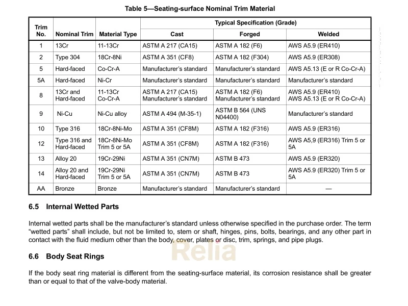
5.9.1 The packing may be square, rectangular, or trapezoidal in cross-section. The nominal radial width of the packing, w, shall be in accordance with Table 5 and Table 6 for respective units (metric/U.S. Customary).
5.9.2 The nominal depth of the packing box shall accommodate a minimum of five uncompressed rings of packing. Unless otherwise specified by the purchaser, the packing box surface area in contact with the packing materialshall have a surface finish, Ra, of 4.5 µm (175 µin.) or smoother.
5.9.3 The maximum bore (inside diameter) of the packing box shall be the sum of the nominal valve stem diameter plus twice the nominal packing width plus a clearance factor, y, i.e., equal to d n + 2w+ y. See Table 5 and Table 6 for the required values.
5.9.4 A gland and a separate gland flangeshall be provided for packing compression. The gland flangeshall have two holes to receive the gland bolting. Slots for gland flange bolts shall not be used. The gland and gland flangeshall be self-aligning. The glandshall have a shoulder at its outer edge so as to prevent complete entry of the gland into the packing box. Packing gland assembly (including gland flange, follower, bolting, and anchoring pins) shall have adequate strength to transmit load without permanent deformation under required packing load.
5.9.5 A lantern ringshall be provided only if so specified by the purchaser. To accommodate the lantern ring, the packing box depth shall be at least equivalent to that of a minimum of three uncompressed rings of packing above the lantern ring and three uncompressed rings of packing below the lantern ring plus the length of the lantern ring.
5.9.6 The clearance between the packing box bore (inside diameter) and the outside diameter of the gland (see Figure C.1) shall be nominally less than the diametrical clearance between the inside diameter of the gland and the stem diameter.
5.9.7 See 5.13 for additional packing requirements.
5.10 Bolting
5.10.1 Bolting shall be standard inch series bolting, except if the purchaser specifies metric series bolting. Bolting for the bonnet-to-body jointshall be continuously threaded stud bolts with heavy, semi-finished hexagon nuts that are in accordance with ASME B18.2.2 or ASME B18.2.6M.
5.10.2 Yoke-to-bonnet bolting shall be either continuously threaded stud bolts or headed bolts with hexagon nuts.
5.10.3 Gland bolts shall be hinged eyebolts, headed bolts, stud bolts, or studs. Hexagon nuts shall be used.
5.11.4 The handwheelshall be retained on the stem nut by a threaded handwheel nut. The handwheel connection to stem nut shall be designed to prevent loosening due to normal service or vibration.
5.11.5 If operation by a chain wheel, gearbox, or power actuator is to be added to the valve, the purchaser shall specify the following, as applicable:
— for chainwheel operation, the dimension from the centerline of the valve stem or gear input shaft to the bottom of the chain loop;
NOTE Chainwheels may present a risk of injury or damage if not properly designed, installed, secured, operated, and maintained.
— spur or bevel gear and the position of gearing handwheel relative to the pipe axis;
— electric, hydraulic, pneumatic, or other actuator type;
— maximum service temperature and pressure differential across the valve disc;
— power supply attributes for power actuators.
5.11.6 Valve-to-gear-box or power actuator flange mating dimensions shall be according to ISO 5210 or MSS SP-102, or shall comply with the purchaser’s specifications.
5.12 Bypasses and Other Auxiliary Connections
Auxiliary connections to the body and/or bonnet, such as drains, shall be furnished only if specified on the purchase order. The design and construction of the joint and the piping of auxiliary connections shall conform to the requirements of ASME B16.34. When required for valve DN 50 (NPS 2) or larger, auxiliary connections shall be sized and located as specified in ASME B16.34. The size and location of auxiliary connections shall be indicated on the purchase order.
5.13 Fugitive Emission Design Requirement
5.13.1 The valve shall be type tested to the requirements of API 624.
5.13.2 Packing that meets the qualification requirements of API 624 shall be used unless otherwise specified by the purchaser. Refer to 8.2.2 and 8.2.3 for marking requirements.